Mk 45 Mod 4 IWM Study
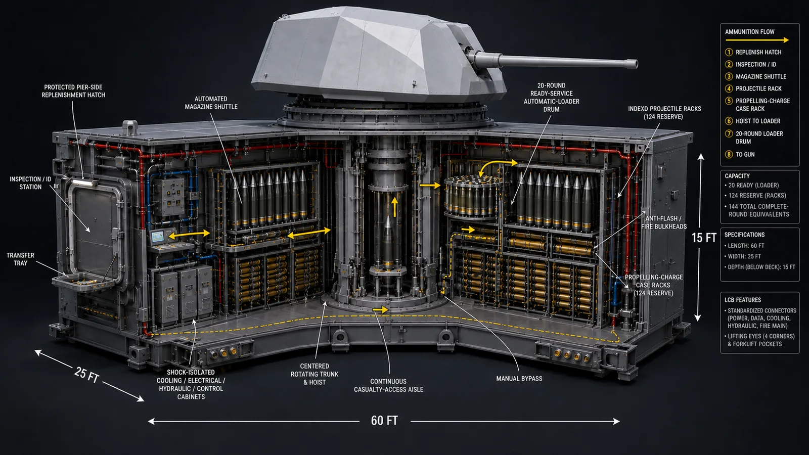
The IWM includes the gun and its supporting magazine, handling, protection, access, and ship-service interfaces; it is not merely a deck-mount adapter.
Permanent hull bays established during construction for build-selected IWM and IMM installations.
Technology 2
Purpose: provide a fleet-standard structural and service envelope for heavy weapons and deeply integrated mission systems without redesigning the hull.
Construction rule: every LCB location, structural boundary, foundation, access route, and service trunk is built permanently into the hull during construction. The LCB itself is never removed, relocated, or exchanged.
Payload rule: the IWM or IMM installed in each bay is selected at build. It is not a port-swappable package; any later payload change requires a certified major refit, hull access, engineering review, and full recommissioning of the affected system.
Back to LCB in the Technology Catalog | Open IWM/IMM Insertion Animation
These maps show the locked structural zones carried into detail design. FFG deck bays remain longitudinal. DDG and CAG designated deck bays rotate crosswise. Every stern slide-in LCB remains longitudinal: 60 ft runs fore-to-aft, 25 ft runs port-to-starboard, and 15 ft runs vertically, with an aft-facing opening at the waterline.
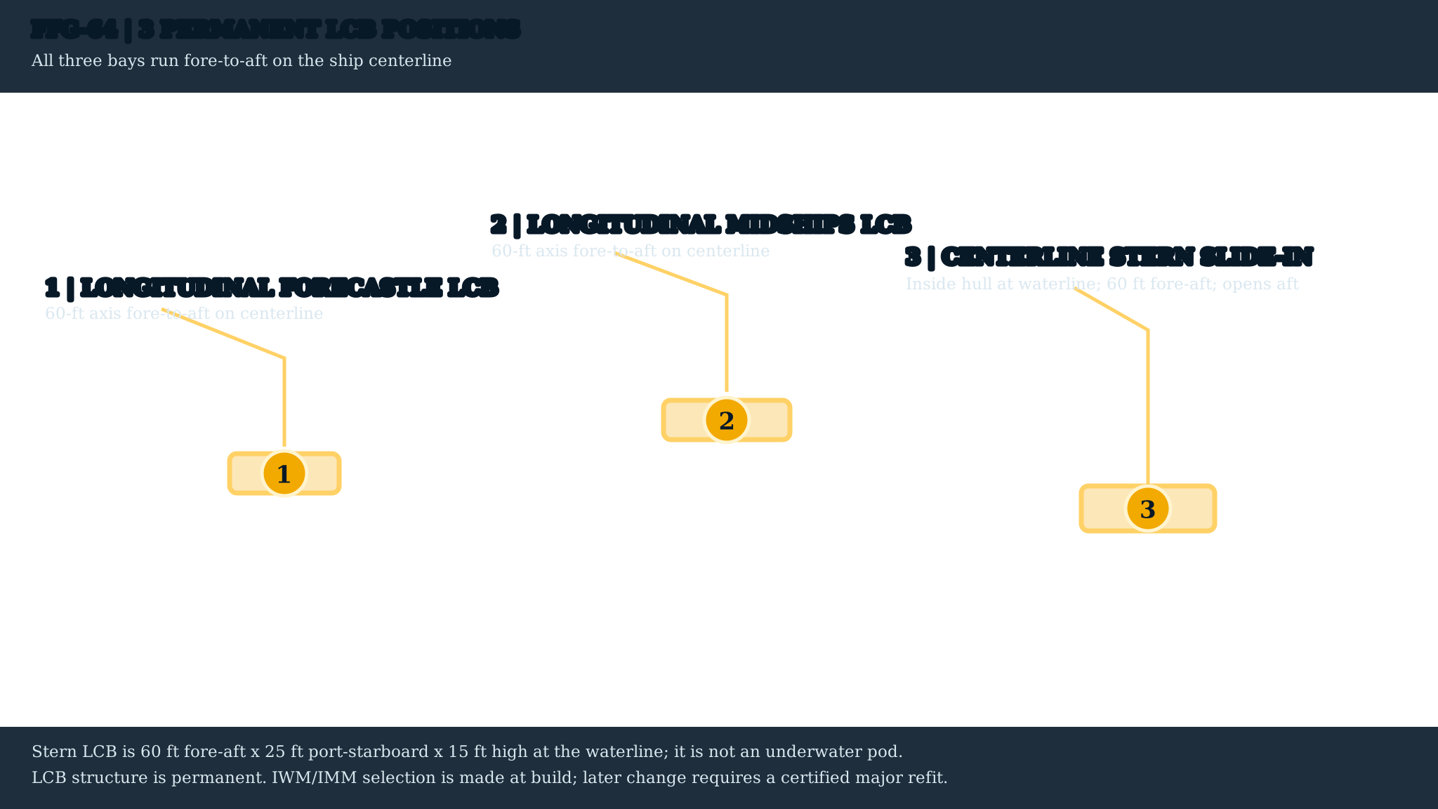
FFG-64: three longitudinal centerline LCBs: 1 forecastle, 1 midships, and 1 stern slide-in bay.
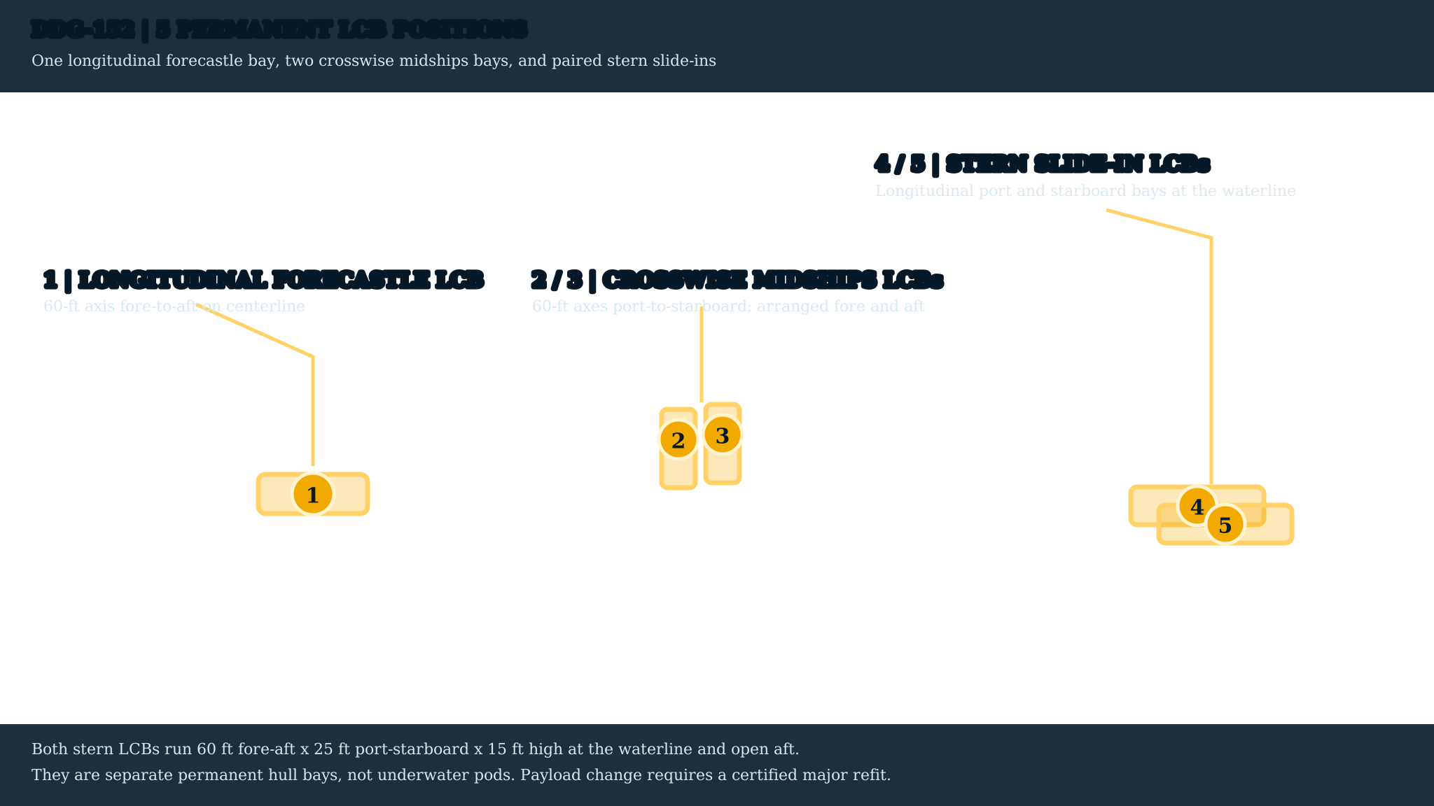
DDG-152: five permanent LCBs: 1 longitudinal forecastle bay, 2 crosswise midships bays arranged fore and aft, and 2 longitudinal stern slide-ins arranged port and starboard.
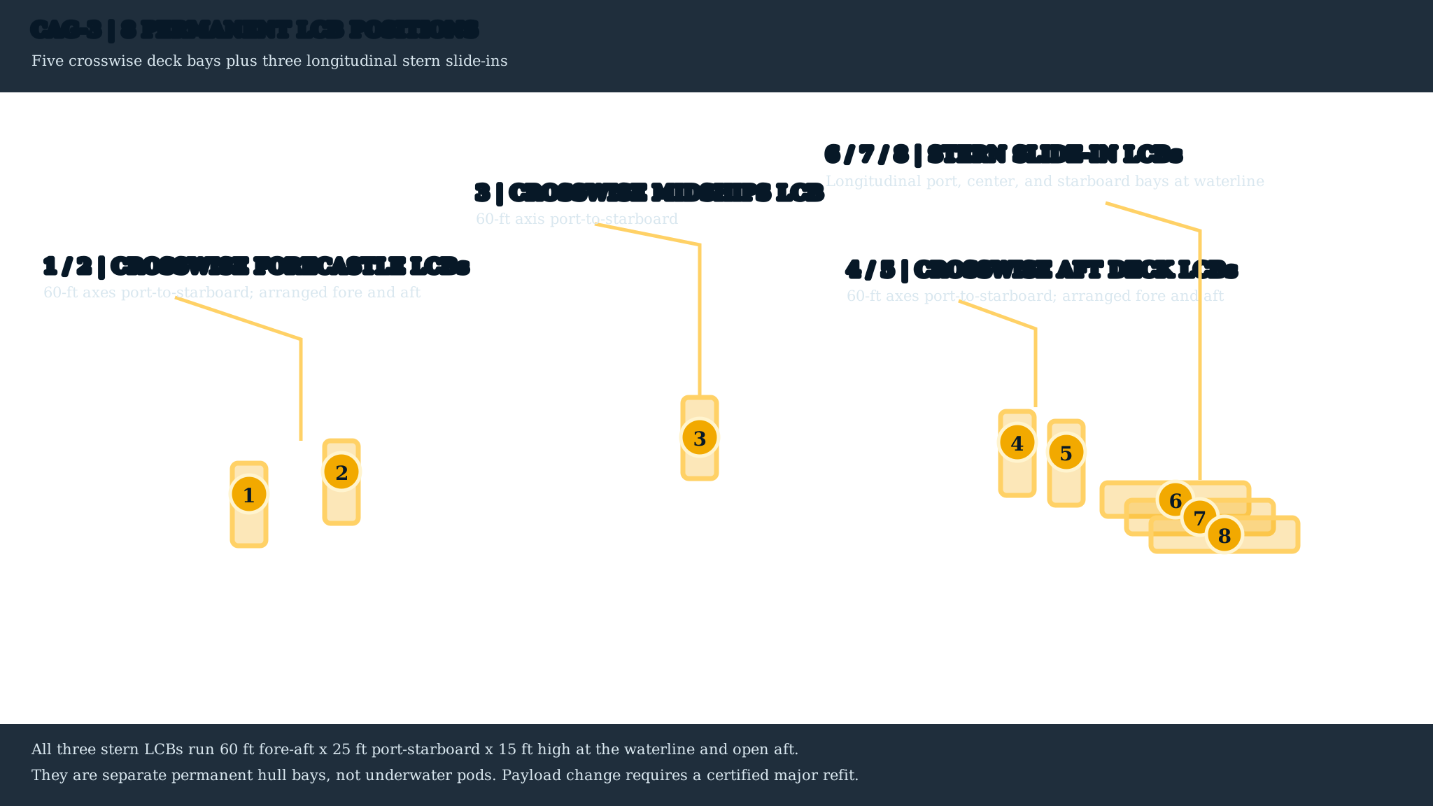
CAG-3: eight permanent LCBs: 2 crosswise forecastle, 1 crosswise midships, 2 crosswise aft-gun-deck, and 3 longitudinal stern slide-ins.
The stern installations use the same 25 ft bay width and 60 ft fore-aft depth without consuming the full hull beam. The FFG centers one bay, the DDG carries two side-by-side bays, and the CAG carries three side-by-side bays, all at the same waterline elevation.
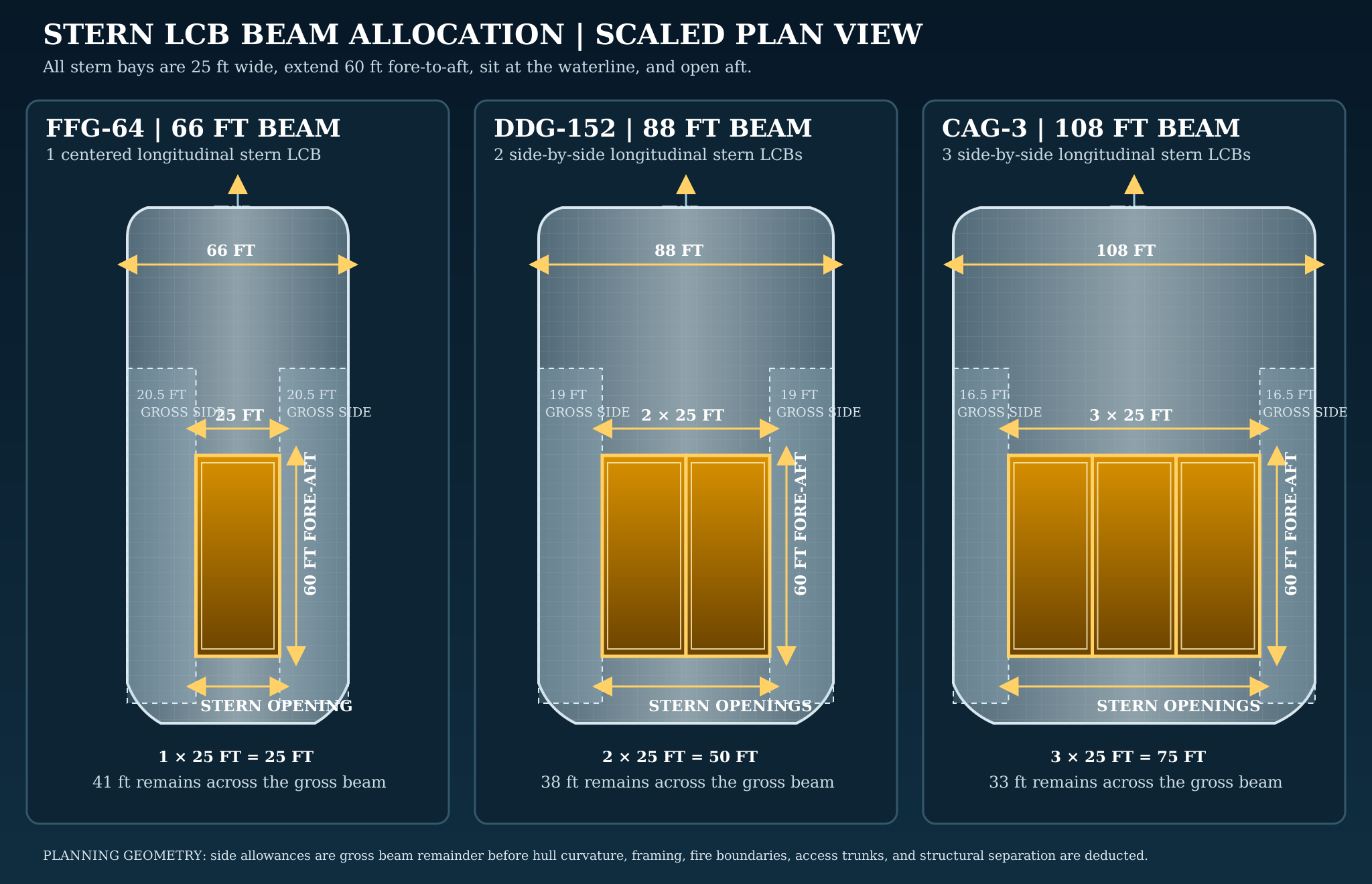
Gross beam allocation: the FFG retains 41 ft total outside its single bay, the DDG retains 38 ft total outside its two bays, and the CAG retains 33 ft total outside its three bays. Final clearances are reduced by hull curvature, framing, fire boundaries, access trunks, and structural separation.
These aft-quarter studies distinguish three separate structures: the enclosed aviation hangars, the raised 01-level flight deck, and the longitudinal stern LCB openings at the waterline. The DDG and CAG aft guns remain on their lower 00-level gun decks forward of the stern openings; no Trinion installation occupies a stern slide-in LCB.
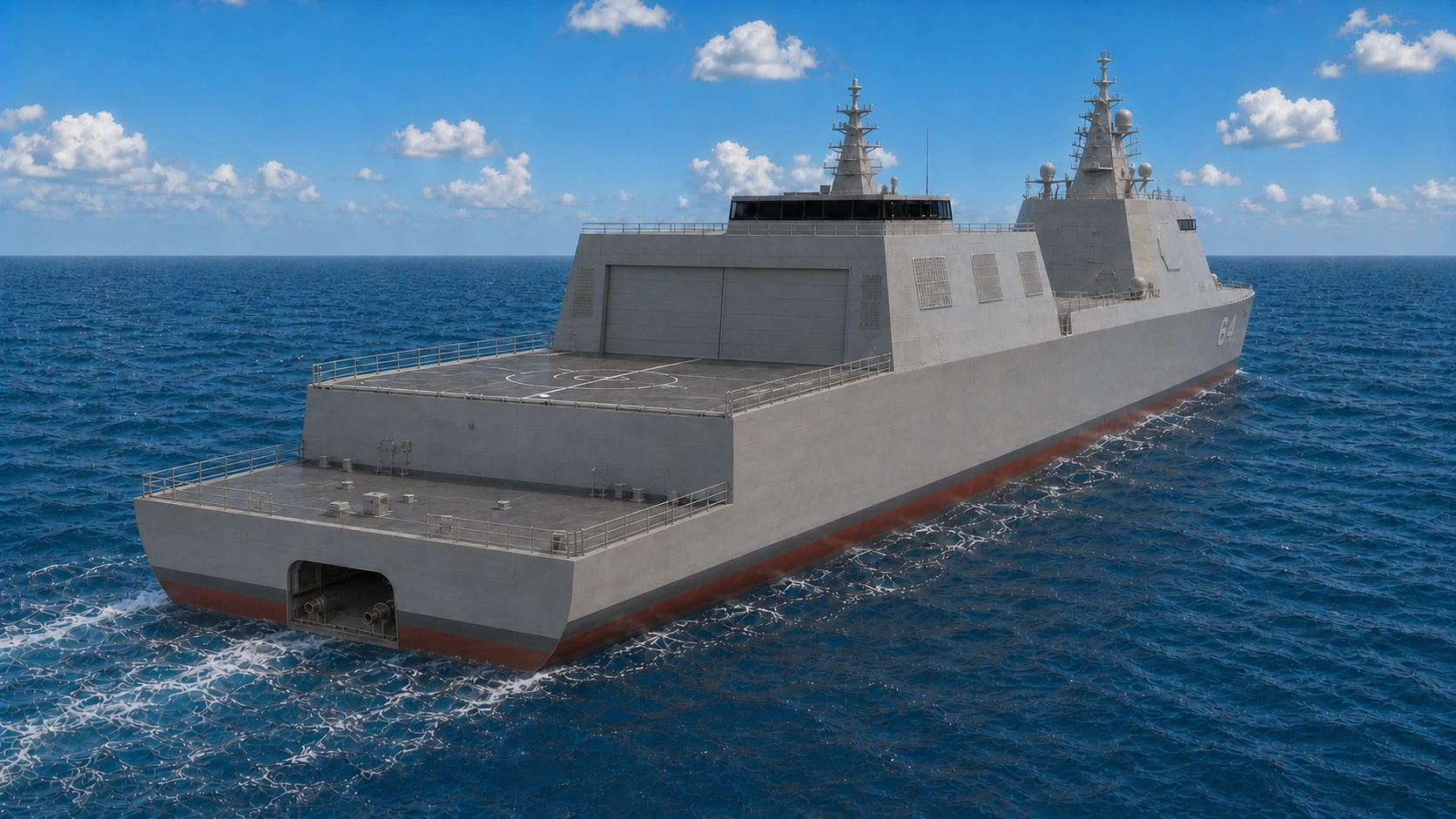
FFG-64: 66-ft beam, 2 enclosed MH-60 hangars, and 1 centered stern LCB. UAV maintenance and mission preparation use shared aviation-support spaces rather than a third full hangar.
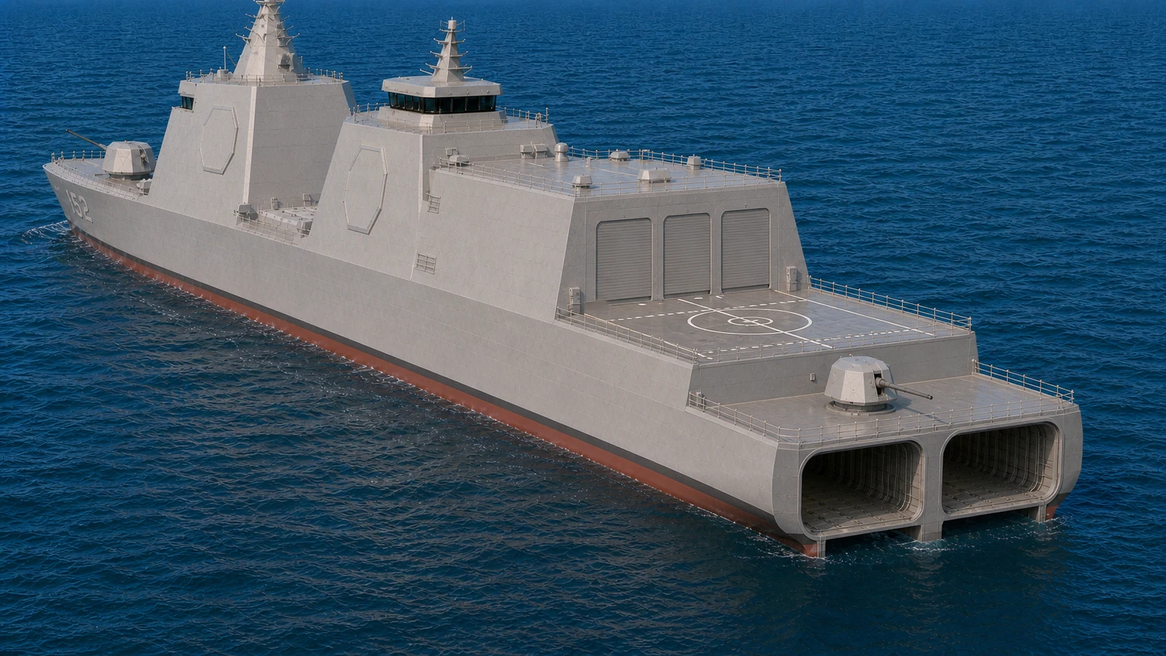
DDG-152: 88-ft beam, 3 enclosed hangars, and 2 side-by-side stern LCBs. The centerline aft gun remains on the separate 00-level gun deck forward of the stern openings.
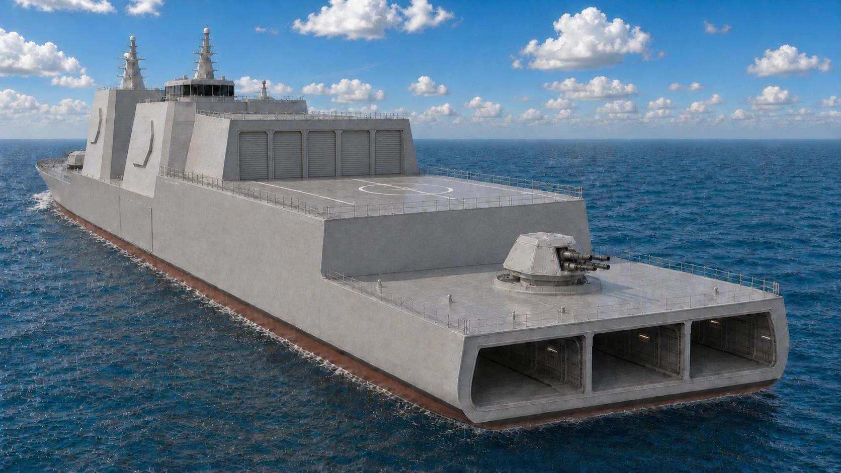
CAG-3: 108-ft beam, 5 enclosed hangars, and 3 side-by-side stern LCBs. Shared Viper and Venom bays plus 3 individual MH-60 bays store all 7 baseline manned helicopters.
| Class | Permanent LCB Count | Locked Structural Locations | Construction Control |
|---|---|---|---|
| FFG-64 | 3 | 1 longitudinal forecastle; 1 longitudinal midships; 1 longitudinal stern slide-in | All three positions lie on the centerline with the 60-ft axis fore-to-aft |
| DDG-152 | 5 | 1 longitudinal forecastle; 2 crosswise midships; 2 longitudinal stern slide-ins | Midships bays are arranged fore and aft; stern bays are arranged port and starboard |
| CAG-3 | 8 | 2 crosswise forecastle; 1 crosswise midships; 2 crosswise aft-gun-deck; 3 longitudinal stern slide-ins | Crosswise pairs are arranged fore and aft; stern bays are port, center, and starboard |
Configuration control: the location count is fixed. Choosing Trinion, Mk 45 Mod 4, VLS, APM, railgun, mission infrastructure, or another certified IWM/IMM does not create a new bay or move an existing one.
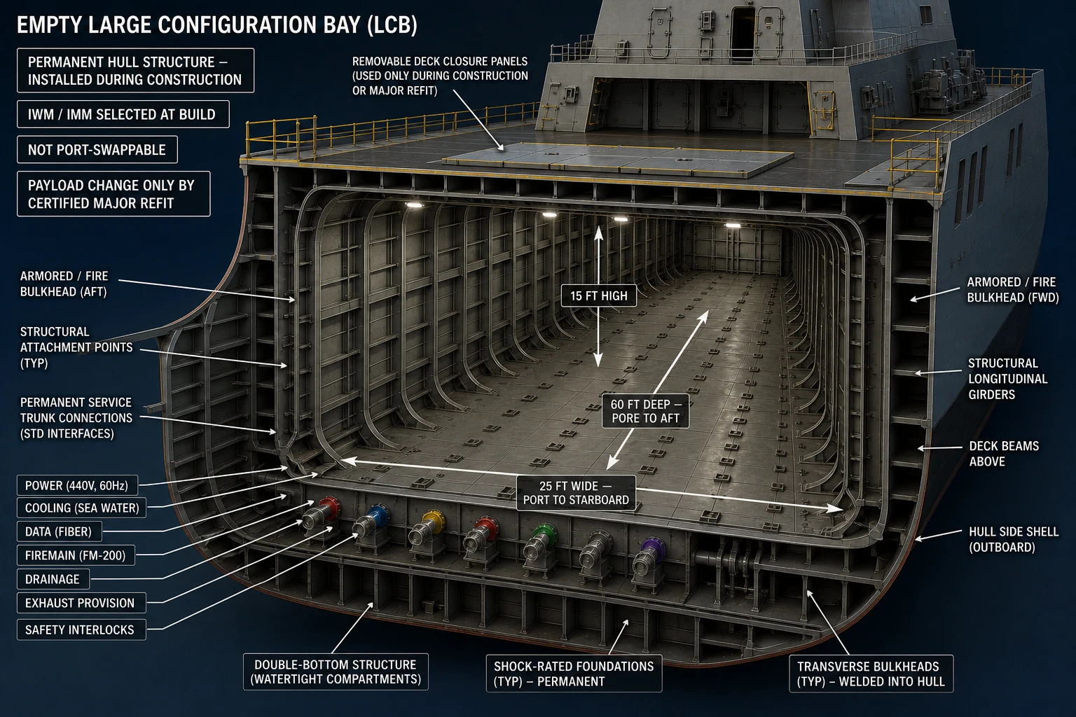
An empty standard LCB is 60 ft x 25 ft x 15 ft. Longitudinal positions extend 60 ft fore-to-aft; designated crosswise deck positions rotate the same structural envelope 90 degrees. Its welded framing, shock-rated foundations, fire boundaries, and capped common services are installed during construction; it is not a removable container or port-swappable module.
IWMs are deeply integrated combat-power installations selected for permanent LCB positions at build. A later IWM replacement is an authorized drydock major-overhaul/refit alteration, not a routine module swap. The permanent bay, foundations, access, and common structural, power, cooling, data, exhaust, fire-protection, handling, and software interfaces allow a future weapon to be designed against a controlled fleet standard. That pathway does not guarantee fit: every new or replacement IWM still requires ship-specific engineering and recertification.
The IWM includes the gun and its supporting magazine, handling, protection, access, and ship-service interfaces; it is not merely a deck-mount adapter.
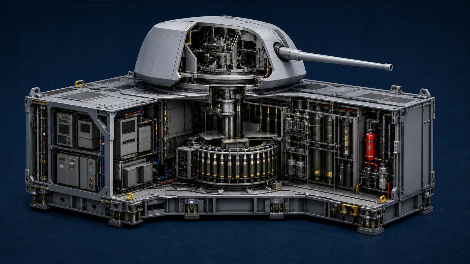
The optional Mk 75 package integrates the compact gun with its magazine, ammunition handling, local controls, cooling, fire protection, and fleet-standard LCB connections.
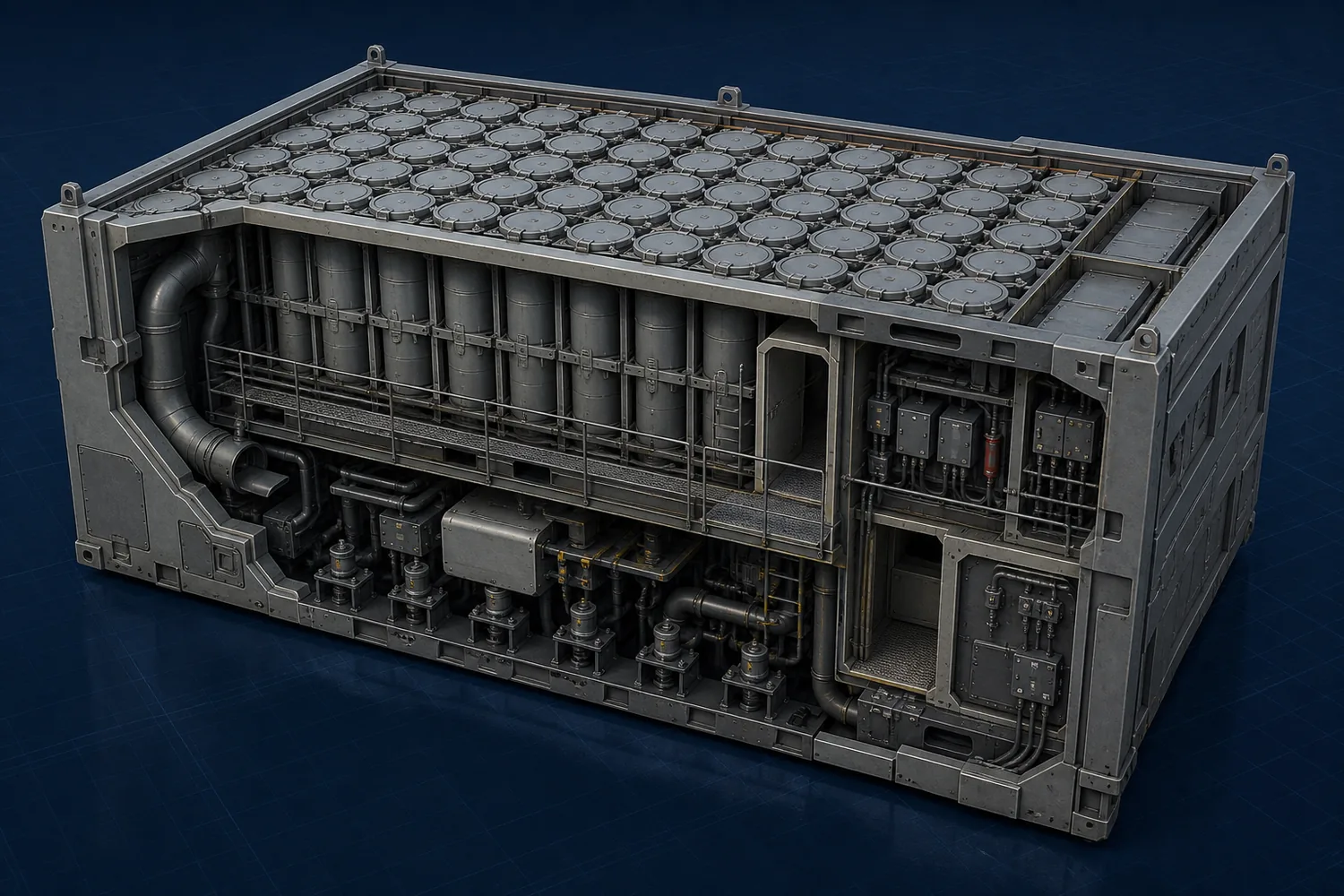
The compatibility IWM is an engineered launcher installation inside the permanent LCB, not loose cells placed into a generic bay.
Every TriSeadon class preserves three potential launcher paths for a future Navy-certified SLCM-N: Mk 41 VLS Compatibility IWM, Mk 57 PVLS IWM, or a dedicated adapter/canister in the APM Large-Payload IWM. These are reserved integration paths, not current certifications. Final selection must wait for the Navy's SLCM-N missile, launcher, and canister interfaces, followed by ship-specific safety, launch-control, nuclear-surety, handling, security, and operational certification. Open the complete SLCM-N integration boundary.
IMMs are deeply integrated mission-infrastructure installations selected for permanent LCB positions at build. A later IMM replacement is an authorized major-refit alteration, not a routine module swap.
LCB-installed IWMs and IMMs are deeply integrated, semi-permanent systems. ISO Mission Modules are separate rapid-change packages for temporary mission needs and use dedicated ISO deck positions.