New Technology Catalog (13 New Systems)
Technology policy: build now, grow throughout life. Initial ships use mature systems and certified fallbacks available to current U.S. shipbuilders; construction does not wait for developmental technology. Protected space, weight, stability, power, cooling, data, access, and interface margins are governed as fleet assets. New systems enter only after engineering, test, safety, integration, and production-readiness gates are passed, then spread through later ships and scheduled refits without reopening the hull design.
Click any technology title to open its dedicated page.
1. Semi-Common Hull Family Architecture
Open dedicated page for this technology
What It Is
- A new TriSeadon hull family designed from first principles, then scaled by class (FFG, DDG, CAG) instead of reusing legacy hulls.
- Class scale baseline from the Triseadon hull design update: FFG about 500 ft x 66 ft, DDG about 650 ft x 88 ft, CAG about 800 ft x 108 ft.
- Common geometry and structural logic across all classes to preserve hydrodynamics, survivability behavior, and internal arrangement logic.
- Double-hull protection and compartmentalization path described in source material, with class-scaled armor and damage-control zoning.
- LCB/IMM/IWM integration spaces are built into the hull from first steel cut, not treated as later add-ons.
Why We Are Doing It
- Eliminate the cost and schedule drag of retrofitting old hulls for new systems.
- Create one semi-common architecture that preserves common parts, interfaces, and training continuity without forcing all three classes into the same hull behavior.
- Keep modernization inside module/refit cycles so ships evolve without structural hull redesign.
Used Today / What It Counters
- Design direction: conservative, seaworthy flared monohull evolution (Spruance/Ticonderoga/Burke line) over exotic tumblehome/high-speed geometry.
- Used today: U.S. programs still rely heavily on legacy hull forms with major retrofit pressure as systems grow.
- Counters: class-unique hull divergence, redesign-heavy upgrades, and schedule risk caused by immature tech gating ship construction.
Current Stop Gap
- No hull-design stop-gap in TriSeadon baseline; the semi-common architecture approach is a flight-start rule, not a later correction.
- Where propulsion maturity requires, early flights can use shaft/rudder with hull geometry preserved for later pod integration in planned refit windows.
Next Flight Implementation Steps
- Lock shared interfaces, structural rules, and selected common parts across all three classes while preserving class-specific hull forms.
- Preserve FFG quieting bias, DDG speed/maneuver bias, and CAG stability/flat-deck bias as separate design priorities.
- Complete model-basin and survivability validation gates, then freeze build standards for GOGO/GOCO/COCO yards.
- Maintain five-year refit discipline so upgrades occur through modules/interfaces, not hull redesign.
Options and Styles
- Hull Styles: semi-common family with class-specific hull forms rather than one identical hull stretched across all missions.
- Scale Styles: FFG near Flight III Burke size, DDG larger than Zumwalt, CAG in heavy-cruiser/battlecruiser pocket-battleship scale.
- Protection Styles: double-hull zoning, compartmentalization, and class-scaled armor allocations.
- Propulsion Integration Styles: shaft/rudder transitional fit or pod-ready integration with preserved hull architecture.
- Modernization Style: structural continuity with module-driven upgrades every block/refit cycle.
Mounting and Integration Particulars
- Hull is built with permanent LCB and interface infrastructure from day one to receive IWMs/IMMs/ISO-connected systems.
- Shared interface standards keep modules portable across classes and yards while avoiding the mistake of forcing one hull behavior across ASW, AAW, and command-heavy roles.
2. LCB Architecture (IWM + IMM)
Open dedicated LCB technology page
Open Class Placement Renderings | Open Stern Beam Layout | Open Empty Permanent Bay
Open IWM List | Open IMM List
Open IMM / IWM Animation
What It Is
- LCB geometry reference: 60 ft long x 25 ft wide x 15 ft standard-height permanent hull bay.
- Class allocation baseline: FFG 3 LCB positions, DDG 5 LCB positions, CAG 8 LCB positions.
- Placement baseline: FFG (3 longitudinal centerline bays: forecastle, midships, stern slide-in); DDG (1 longitudinal forecastle, 2 crosswise midships, 2 longitudinal stern slide-ins); CAG (2 crosswise forecastle, 1 crosswise midships, 2 crosswise aft-gun-deck, 3 longitudinal stern slide-ins).
- Orientation rule: longitudinal bays run 60 ft fore-to-aft by 25 ft port-to-starboard. Crosswise deck bays rotate 90 degrees. Stern slide-ins always remain longitudinal at the waterline and open aft.
- LCB use: integrated module bays for IWM (Integrated Weapon Modules) and IMM (Integrated Mission Modules).
- Permanent-structure rule: LCB locations, foundations, boundaries, access, and common services are installed during construction and never moved or swapped afterward.
- IWM role: deeply integrated weapon, launcher, and combat-support installations selected at build; any later replacement is a certified major-refit alteration.
- IMM role: deeply integrated mission infrastructure selected at build; any later replacement is a certified major-refit alteration.
- Future-tech contract: new heavy weapons and integrated mission systems must fit certified single-LCB or approved double-LCB envelopes rather than forcing hull redesign.
Why We Are Doing It
- Enable controlled heavy-system insertion without hull redesign.
- Push future engineering into payload certification against common interfaces instead of repeating structural redesign for each new weapon, sensor, or mission system.
- Keep all classes on the same physical interfaces, parts ecosystem, and workforce model.
Used Today / What It Counters
- Used today: modular refit logic and containerized mission support are already applied in current naval programs.
- Counters: redesign-driven delays by separating hull production from system maturity.
Current Stop Gap
- Traditional bespoke integrations and limited modular interoperability across legacy classes.
Next Flight Implementation Steps
- Lock LCB dimensions and shared hookups (power, cooling, data, firefighting).
- Enforce IWM/IMM interface certification before production insertion.
- Execute any authorized IWM/IMM replacement only through scheduled major-refit engineering and recommissioning playbooks.
Options and Styles
- IWM Options: Trinion-H, Trinion-L, Mk 45 Mod 4, Mk 75 76 mm gun, conditional Mk 51 AGS, Mk 41 VLS compatibility, Mk 57 PVLS, APM large-payload, developmental railgun, future DEW, and Navy-certified counter-hypersonic IWMs after integration and qualification.
- IMM Options: ASW/UUV/USV integration, mine warfare, RHIB/SOF, amphibious assault lift, drug interdiction/LEDET, anti-piracy/VBSS, VDS/towed array, fuel/logistics, medical/command, DEW/counter-air, workshop, VLS reload, and UMV attack modules.
- Installation Style: LCB structures are permanent build-installed hull features. IWMs and IMMs are build-selected systems; replacement requires a certified major refit.
Mounting and Integration Particulars
- IWMs/IMMs are LCB-based drydock installations with deep ship integration.
3. ISO Rapid Mission Modules
Open dedicated ISO technology page
Open ISO Mission Module List
Open ISO Port-Swap Animation
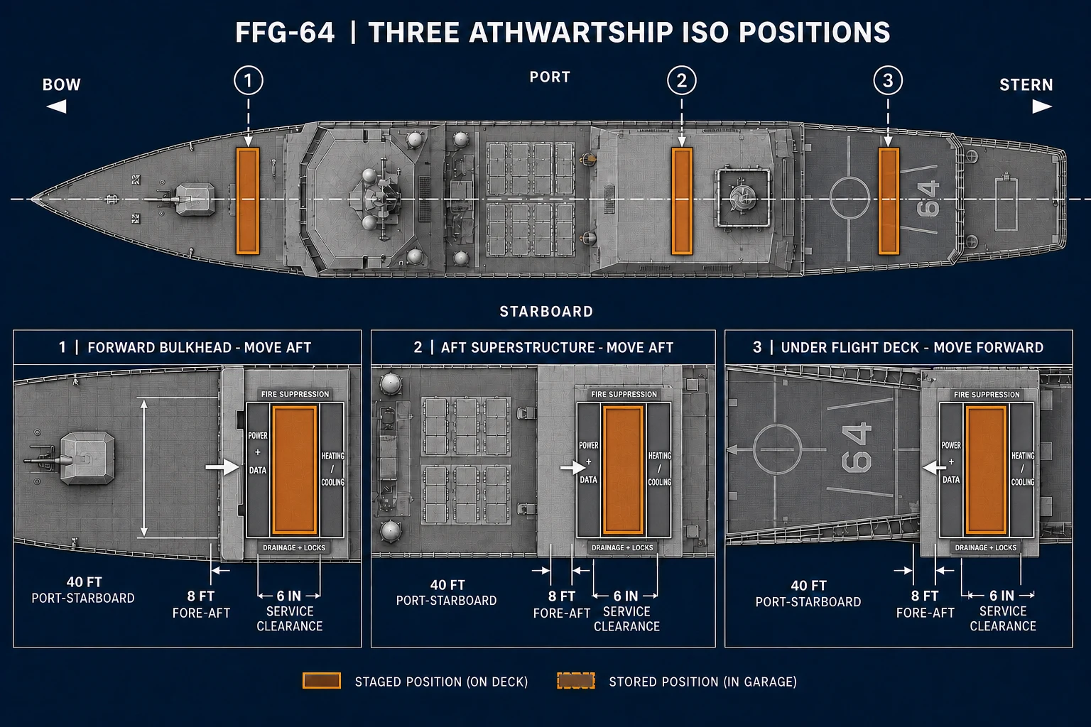
FFG ISO garage baseline: all three 40 ft x 8 ft x 8 ft 6 in modules remain athwartship, with the 40-foot dimension running port-to-starboard. Each module moves only its 8-foot fore-aft depth through a close-fitting roll-up bulkhead door and stops immediately inside. Approximately six inches of service clearance surrounds the module; power, data, heating and cooling, fire suppression, drainage, and locking equipment are built tightly around the standardized enclosure.
What It Is
- ISO modules are mission-specific, standard-container-sized packages installed in dedicated deck slots.
- Class allocation baseline: FFG 3 ISO slots, DDG 5 ISO slots, CAG 8 ISO slots.
- ISO modules use standardized power, data, cooling, firefighting, securing, and environmental connections.
- They are rapid-change mission packages exchanged in port without drydock, hull opening, or a major refit.
- ISO modules do not replace the semi-permanent heavy integration role of LCB-installed IWMs and IMMs.
Why We Are Doing It
- Allow rapid mission changes for EW, counter-UAS, communications, unmanned systems, humanitarian support, workshops, survey, and other temporary needs.
- Separate short-notice mission configuration from the ship's semi-permanent weapon and mission architecture.
Operating Rule
- ISO packages are loaded, connected, tested, and certified at an equipped port.
- Mission selection may change frequently, but the locked number of ISO positions on each class does not change without baseline authorization.
- ISO payloads must bring any package-specific support burden that exceeds the ship's standard slot services.
Representative Options
- Drone swarm, UAV support, loitering munition, EW/SIGINT, counter-UAS, communications relay, cyber, underwater survey, disaster assistance, medical isolation, and mobile workshop packages.
4. DMC Drone Monitor and Control Center
Open dedicated page for this technology
What It Is
- Acronym meaning: DMC = Drone Monitor and Control.
- Space type: fully manned shipboard operations center dedicated to drone monitoring, control, and mission management.
- Command role: a completed warfare space similar in status to ATC and CIC, with assigned watch teams and supervisory control authority.
- Control scope: UAV and USV operations plus the fleet-common SeaFox, reusable very-small UUV, and small UUV/Seaglider-family package, with real-time sensor, routing, payload, launch, recovery, charging, and mission-data management.
- Integration points: cross-wired with CIC, Bridge, and ATC for coordinated task-group operations and engagement support.
- Program baseline: DMC is built into all TriSeadon hulls from first construction flight.
Why We Are Doing It
- Establish dedicated, staffed drone command-and-control as a core warfighting function.
- Support all-class unmanned operations with consistent command authority and workflows.
- Prevent drone operations from being treated as an afterthought inside already overloaded CIC or ATC watch teams.
Used Today / What It Counters
- Used today: unmanned operations are often managed through distributed CIC/ATC workflows.
- Counters: fragmented drone command-and-control by creating a dedicated warfare space and watch structure.
Current Stop Gap
- No stop-gap in TriSeadon baseline; DMC is an original flight-start requirement across all classes.
Next Flight Implementation Steps
- Finalize DMC watchbill, authority model, and integration with CIC/Bridge/ATC.
- Certify UAV/USV/UUV control and launch-recovery procedures by class.
- Align fleet training/certification pipelines to the built-in DMC baseline from first hull onward.
Options and Styles
- Control Options: UAV, USV, and UUV mission management from a dedicated warfare space.
- Command Styles: ship-local control, task-group coordination, and delegated mission-control handoff.
- Mission Styles: ISR monitoring, EW support, route/payload control, and launch/recovery management.
- Class Density Styles: FFG emphasizes ASW and scout-unmanned control, DDG emphasizes relay and defensive network support, and CAG carries the heaviest multi-domain drone monitoring and control burden.
Mounting and Integration Particulars
- Integrated command-space architecture tied to One-Consul, CIC, Bridge, and ATC.
- Mission packages can be expanded via IMM/ISO unmanned modules by class need.
- DMC is a baseline warfare space from first hull, not a future tech experiment or optional command add-on.
5. AEGIR Adaptive Energy Grid
Open dedicated page for this technology
What It Is
- Acronym meaning: AEGIR = Adaptive Energy Grid Integration & Redundancy.
- Function: integrated ship power distribution and redundancy control.
- Inputs: LM2500+G4 gas-turbine generation, PA6B STC diesel generation, and PRIME battery reserve modules.
- Class allocation: FFG and DDG each carry two separated AEGIR distribution sections; CAG carries three.
- Behavior: zonal isolation/reconfiguration under damage and high-load conditions.
- Purpose: support propulsion, sensors, combat systems, and DEW growth margins.
Why We Are Doing It
- Create one resilient fleet-wide power management standard for combat survivability.
- Support future payload growth without repeated class-specific rewiring efforts.
Used Today / What It Counters
- Used today: Flight I uses proven IPS-derived architecture while AEGIR standardization is phased in.
- Counters: brittle power architectures that cannot reconfigure quickly under battle damage.
Current Stop Gap
- Proven IPS-derived architectures on Flight I with AEGIR functionality phased in.
Next Flight Implementation Steps
- Finalize common AEGIR interface and control standards across classes.
- Run integration tests with PRIME, propulsion controls, and mission-load profiles.
- Certify reconfiguration drills and failure-mode behavior before block rollout.
Options and Styles
- Operating Styles: normal efficiency mode, combat surge mode, and casualty isolation/reconfiguration mode.
- Integration Options: turbine, diesel, and PRIME reserve integration under one control architecture.
- Resilience Style: zonal isolation and load-priority control for weapons, propulsion, and survivability systems.
Mounting and Integration Particulars
- AEGIR is a shipwide control/integration architecture, not an external mount.
- Interfaces directly with PRIME modules, propulsion controls, and combat-load priorities.
6. Odyssey Azimuthing Pod Propulsion
Open dedicated page for this technology

Odyssey installation geometry: two common 25 MW continuous / 27 MW short-duration objective pods shown with removable 360-degree azimuth collars. This illustrates the recess and collar standard; exact class layouts distribute pods longitudinally within the aft portion of each hull.
What It Is
- Core parameter: 360-degree azimuthing electric pod architecture.
- Class configuration: Odyssey pods are rated at 25MW continuous with a 27MW short-duration sprint objective, fully azimuthing and common across all classes, with CAG 4 pods, DDG 3 pods, and FFG 2 pods.
- Common physical envelope: every class reserves the same provisional 40 ft long, up-to-23 ft wide/deep, approximately 375-short-ton pod planning unit, with an 18-22 ft propulsor-diameter allowance, a 20 ft mounting flange, and a 50 ft full-azimuth swept envelope. The enlarged envelope reflects the 25MW rating; detailed FFG fitment and overall navigational draft remain open naval-architecture checks.
- Hull integration style: mounted into spooned aft hull sections using counter-rotating screws to reduce draft where possible without giving up cavitation control, seaworthiness, ASW flow quality, or efficiency.
- Placement baseline: FFG uses a slightly staggered port/starboard pair in the aft quarter; DDG uses 2 aft plus 1 centerline-forward pod inside the aft 25-30 percent; CAG uses independently zoned forward and aft pairs inside the aft third.
- Benefits: maneuverability, acoustic control, and machinery-layout flexibility.
- Transition path: early FFGs can use shafts/rudders before full pod rollout.
- CAG transition note: first 2-3 CAG hulls may use shaft/rudder if Odyssey approval is not complete at build start.
Why We Are Doing It
- Improve maneuverability and acoustic performance for contested maritime operations.
- Standardize propulsion growth path across all three classes.
Used Today / What It Counters
- Used today: azimuthing pod architectures are proven in commercial practice and adapted in military transition pathways.
- Counters: maneuver and acoustic limitations of fixed shaft/rudder-only configurations.
Current Stop Gap
- Shaft/rudder propulsion remains authorized until Odyssey pod qualification is complete.
Next Flight Implementation Steps
- Complete qualification and survivability testing for pod systems.
- Stand up yard tooling, workforce certification, and spare-parts support for pods.
- Introduce on next eligible flight and expand by block once readiness gates are met.
Options and Styles
- Configuration Options: all Odyssey pods share the 25MW continuous / 27MW short-duration objective rating, all are 360-degree azimuthing, and all are the same fleet-standard interchangeable propulsion unit.
- Transitional Style: shaft/rudder fallback for early flights while preserving later pod insertion paths.
- Mission Styles: high-maneuver profile, low-acoustic profile, and endurance/cruise profile.
- CAG Refit and Reassignment Options: early shaft/rudder CAG hulls can convert to Odyssey during refit or, when combat-service needs and hull condition warrant, undergo purpose-engineered conversion for auxiliary roles such as a medical or hospital ship, troop transport, amphibious-support ship, or UNREP and fleet-logistics ship.
Mounting and Integration Particulars
- Installed as identical 25 MW continuous / 27 MW short-duration objective propulsion modules; pod count and stationing vary by class, but pod dimensions, power rating, mounting interface, and service requirements do not.
- Mounted in spooned aft hull sections with counter-rotating screw geometry and pod placement tuned for draft control, quiet flow, and ASW efficiency.
- All pods retain physical 360-degree azimuth capability, but control software progressively limits steering angle and turning rate at speed. High-speed operation aligns the pods nearly fore-and-aft; full-vector maneuvering is reserved for low-speed and port operations.
- Rendering rule: a pod occupies 8.0 percent of FFG length, 6.15 percent of DDG length, and 5.0 percent of CAG length; its 18 ft width occupies 26.5, 20.5, and 16.7 percent of the respective class beams.
- Each longitudinal station receives separate foundations, watertight boundaries, AEGIR feeds, cooling, controls, and casualty isolation. The FFG also retains an engineering requirement for an independent emergency take-home propulsion path because loss of both primary pods would otherwise leave the electrically powered ship without propulsion.
- Early flights can retain shaft/rudder layouts while preserving later pod integration path.
- Displacement and growth check: Odyssey sizing is aligned to the locked baselines of 10,000 tons for FFG, 15,000 tons for DDG, and 32,000 tons for CAG. The 20 percent limits of 12,000 / 18,000 / 38,400 tons are conditional naval-architecture growth envelopes, not freely assignable payload. Added displacement must pass class-specific weight, stability, draft, freeboard, structure, seakeeping, propulsion, speed, maneuverability, endurance, and acoustic checks.
7. One-Consul Unified Console Architecture
Open dedicated page for this technology
What It Is
- Acronym meaning: ONE = Operational Networked Environment.
- Core function: common operator interface and console baseline across classes.
- Node coverage: Bridge, CIC, ATC, DMC, and engineering support stations.
- Replacement path: ONE-Consul is intended to replace the current console baselines deployed on Ford and Zumwalt pathways.
- Design goal: crew cross-qualification and reduced class-specific training burden.
- Operational value: resilient command continuity under degraded conditions.
Why We Are Doing It
- Give crews a common operating environment across FFG, DDG, and CAG.
- Cut training time and improve watch-team transferability across the fleet.
Used Today / What It Counters
- Used today: CDS-derived console baselines in current fleet pathways (including Zumwalt/Ford families).
- Counters: fragmented class-specific operator environments that slow cross-training and watch transfer.
Current Stop Gap
- CDS console baseline remains in service initially and transitions to One-Consul after formal approval and insertion gates.
Next Flight Implementation Steps
- Lock One-Consul UI and interface standards across Bridge/CIC/ATC/DMC nodes.
- Validate legacy combat-logic access through the standardized console layer.
- Deploy via next-flight installs plus scheduled refit backfits with common training packages.
Options and Styles
- Console Styles: Bridge, CIC, ATC, DMC, and engineering-role profiles on the same baseline architecture.
- Deployment Options: CDS-derived baseline in early flights, then expanded One-Consul functions by block/refit.
- Training Style: one cross-class operator framework with role-based overlays instead of ship-unique consoles.
Mounting and Integration Particulars
- Installed as standardized console/workstation hardware and software interfaces across command spaces.
- Integrated into Bridge/CIC/ATC/DMC with common data/control architecture.
8. Cerberus Universal Mount
Open dedicated page for this technology
What It Is
- Mount type: standardized interface, not a single weapon.
- Power parameter: up to 600kW per mount path in source architecture notes.
- Supports: complete CIWS, RAM/SeaRAM, directed-energy, and allied-compatible terminal-defense packages.
- Boundary rule: Cerberus carries the integrated terminal-defense layer; lighter local-defense weapons and MANPADS use the separate SCUTUM interface.
- Purpose: remove vendor lock and enable rapid defensive reconfiguration.
Why We Are Doing It
- Enable one fleet-standard mount interface for multiple defensive systems.
- Reduce vendor lock and simplify cross-class sustainment and training.
Used Today / What It Counters
- Used today: close-in defense exists fleet-wide, but often through class-specific mount/integration paths.
- Counters: vendor lock and hardwired hull-specific weapon positions that slow upgrades.
Current Stop Gap
- Legacy fixed mount arrangements and class-specific integration pathways.
Next Flight Implementation Steps
- Freeze mechanical, electrical, cooling, and data interface standards.
- Qualify legacy-to-Cerberus adapter paths for CIWS/RAM/SeaRAM continuity.
- Make Cerberus the default mount baseline for next-flight installs.
Options and Styles
- Mount Options: Phalanx-class CIWS, RAM/SeaRAM, HELIOS or other qualified directed-energy systems, and future integrated point-defense systems.
- Integration Style: One government-owned interface standard so mounts are not hardwired to a single hull/vendor path.
- Capability Style: kinetic-only, DEW-only, or mixed defensive belts by mission package and class allocation.
- Partner Style: allied-compatible systems can be adapted without hull redesign.
- Growth Style: fixed-hull baseline remains 3 mounts on FFG, 5 on DDG, and 8 on CAG, and any growth above that costs primary mission capacity. IWM growth trades away primary weapon volume, IMM growth trades away a primary mission module, and ISO growth turns the ISO package itself into a terminal-defense mission fit with its own power, cooling, and control burden.
Mounting and Integration Particulars
- Cerberus is itself the terminal-defense mount standard and can host CIWS, RAM/SeaRAM, and qualified DEW options.
- Inserted as certified mounting architecture under common electrical, cooling, and control interfaces.
9. SCUTUM Light-Defense Mount
Open dedicated page for this technology
What It Is
- SCUTUM: Standardized Close-in Universal Tactical Utility Mount.
- A government-controlled light-weapon hardpoint and service interface for local force protection, small-craft defense, counter-UAS work, and threat-driven MANPADS stations.
- Candidate payloads include Mk 46 or Mk 38-family 30 mm systems, M2 .50-caliber and M240 machine guns, Navy-certified removable MANPADS firing-station packages, and nonlethal water-cannon, acoustic-hailer, searchlight, and warning-device adapters.
- The Latin word scutum means shield, matching the mount's role as the fleet's distributed outer-watch and local-defense layer.
Why We Are Doing It
- Separate numerous light defensive stations from the larger, more expensive Cerberus foundations.
- Give all three classes common foundations, adapter plates, recoil limits, power, data, cueing, corrosion protection, ammunition-service rules, and safety controls.
- Permit weapon replacement or mission reconfiguration without cutting a new foundation into the ship.
Current Baseline and Boundary
- Mk 46 Mod 2 provides a fielded 30 mm bridge path; Mk 38 Mod 4 is the preferred next-production 30 mm integration study.
- Caliber is only a screening guide. System weight, recoil, magazine, sensors, power, cooling, and combat function determine the interface.
- Phalanx remains Cerberus despite its 20 mm gun because it is a complete autonomous CIWS with its own radar, fire control, and terminal-defense function.
- VLS, guns above 75 mm, APM, railguns, and large DEW remain IWM payloads. RAM/SeaRAM, Phalanx, and HELIOS-class systems remain Cerberus payloads.
Engineering and Configuration Rule
- Freeze the SCUTUM load classes, adapter geometry, firing-arc controls, remote/local control, combat-system cueing, ammunition access, and protected ready-locker requirements before ship-detail design.
- Locked physical counts: 6 positions on FFG, 10 on DDG, and 16 on CAG, arranged as balanced port/starboard pairs. Exact locations remain subject to firing-arc, blast, recoil, structural, topweight, aviation-clearance, sensor-interference, and topside-congestion validation.
- A SCUTUM position may be fitted, left capped, or assigned a different certified light payload without changing the locked Cerberus count.
10. APM Hypersonic Launch System
Open dedicated page for this technology
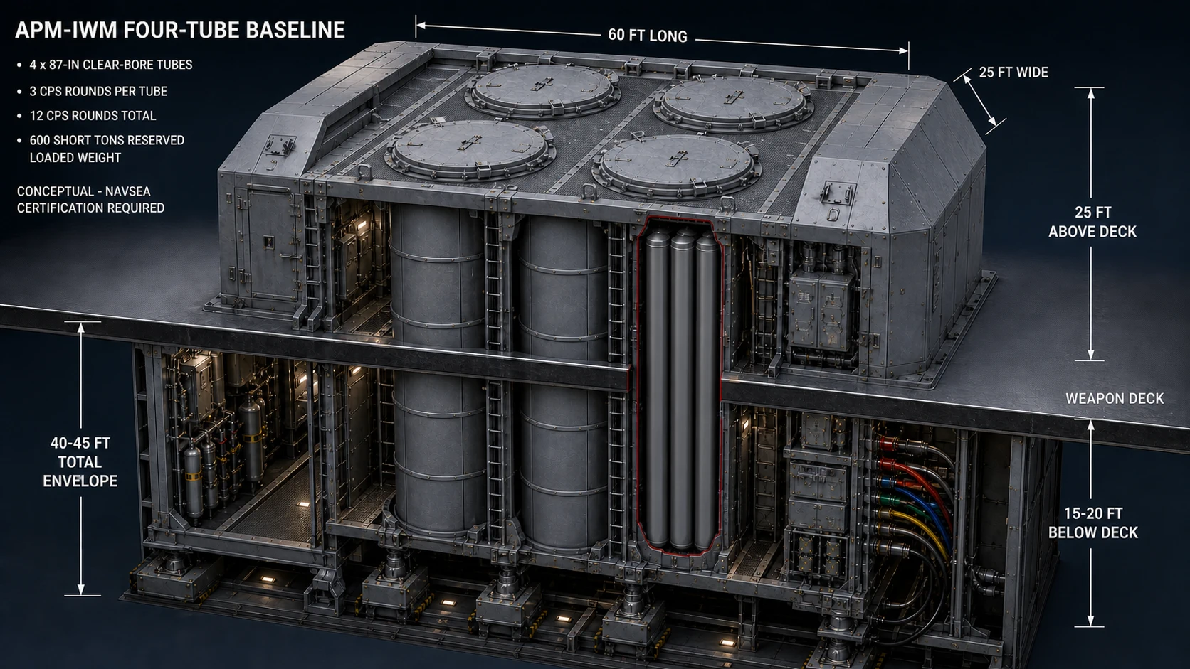
Locked APM-IWM baseline: four 87-inch clear-bore launch tubes in a 2-by-2 arrangement, with three CPS all-up rounds per tube for 12 rounds total. The 60 ft x 25 ft module rises 25 ft above the weapon deck, extends 15-20 ft below it, and reserves a 40-45 ft total integration envelope and up to 600 short tons loaded.
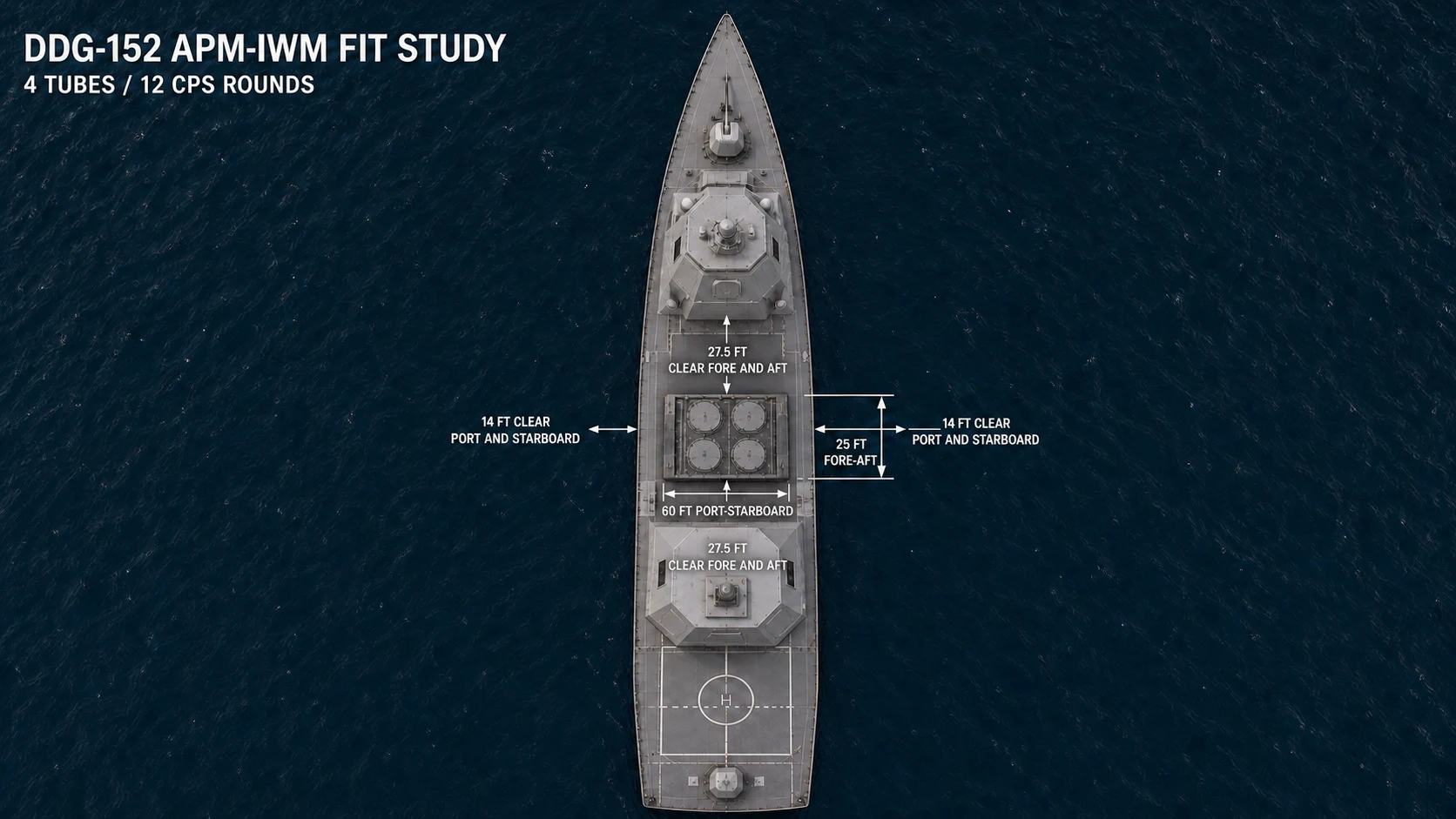
Crosswise DDG installation study: the APM-IWM uses 60 ft port-to-starboard and 25 ft fore-to-aft. One centered module leaves 14 ft gross clearance per side across the 88-ft beam and 27.5 ft gross clearance fore and aft within the 80-ft missile-deck zone.
What It Is
- Acronym meaning: APM = Advanced Payload Module.
- Locked building block: one complete APM-IWM carries four 87-inch launch tubes and three sealed CPS all-up rounds per tube, for 12 rounds total.
- Locked envelope: 60 ft long x 25 ft wide; 25 ft above deck plus 15-20 ft below deck; 40-45 ft total.
- Weight reservation: up to 600 short tons loaded. This is a ship-design allowance, not a published Navy launcher weight.
- Class selection: CAG is the priority host, DDG is a weight- and mission-dependent option, and FFG remains an optional later integration path.
- Deployment alignment: the same CPS weapon family is being integrated through Zumwalt and Virginia modernization tracks, but the TriSeadon surface installation requires separate Navy certification.
- VLS continuity logic: TriSeadon primary VLS is Mk 57 PVLS; stop-gap compatibility is delivered by Mk 41 VLS tubes packaged in certified IWM modules.
- Role: long-range precision strike and strategic fires depth.
Why We Are Doing It
- Add long-range strike depth and strategic fires capacity in a block-controlled pathway.
- Align with ongoing modernization tracks without breaking fleet commonality rules.
Used Today / What It Counters
- Used today: Mk 41 VLS legacy ecosystem is active now across U.S. surface combatants (including Flight III Burke); APM integration path is active on Zumwalt modernization.
- Current constraint: Mk 57 PVLS is the stronger/larger TriSeadon choice, but U.S. missile certification/production for Mk 57 PVLS slowed after Zumwalt truncation to three hulls.
- Counters: long-range strike gaps and insufficient deep-magazine strategic fires options.
Current Stop Gap
- Install Mk 41 VLS tubes as certified IWMs inside TriSeadon LCBs to preserve standard missile compatibility while Mk 57 PVLS missile support scales.
- TriSeadon APMs are also carried as IWMs, aligned to the same APM family being integrated on Zumwalt tracks.
Next Flight Implementation Steps
- Complete launcher/missile availability and integration readiness checks.
- Certify safety, fire-control integration, and loadout doctrine by class.
- Insert in next-flight block allocations (CAG/DDG priority, then FFG path).
Options and Styles
- Loadout Option: one complete four-tube IWM carries 12 CPS rounds; partial two- or six-tube variants are not part of the locked baseline.
- Compatibility Styles: Mk 57 PVLS primary architecture with Mk 41 VLS IWM stop-gap compatibility where required.
- Employment Styles: theater-depth strike, distributed fires, and mixed VLS/APM magazine planning.
Mounting and Integration Particulars
- Fielded as a semi-permanent, build- or major-refit-installed IWM with deep structural integration.
- Cold-gas launch behavior, blast boundaries, shock response, stability, hatches, access, controls, fire protection, and combat-system interfaces require Navy certification.
- Integrated with Mk 57 PVLS primary architecture and legacy compatibility logic during transition.
SLCM-N Reserved Integration Capability
TriSeadon technology position: every class reserves a pathway to carry a future Navy-certified Nuclear-Armed Sea-Launched Cruise Missile (SLCM-N). This is a design-for-integration provision, not a claim that SLCM-N is currently certified for any TriSeadon launcher.
- Mk 41 VLS Compatibility IWM: the most direct study path if the final SLCM-N and canister remain compatible with the Tomahawk-scale Mk 41 VLS strike-length envelope. Mk 41 VLS launches Tomahawk today, but SLCM-N compatibility has not been publicly established.
- Mk 57 PVLS IWM: the primary TriSeadon VLS architecture offers a larger physical growth envelope, but it still requires a Navy-certified canister, launch-control interface, shock and hazard analysis, and live-fire qualification.
- APM Large-Payload IWM: the largest reserved physical path can accept a dedicated future adapter or canister if SLCM-N cannot use Mk 41 VLS or Mk 57 PVLS. APM remains the CPS-priority large-payload installation, so using it for cruise missiles would be a certified mission trade.
- Fleet access: FFG, DDG, and CAG all have LCB/IWM and VLS pathways, but actual carriage would depend on class weight, stability, magazine, security, mission-priority, and deployment-policy decisions.
- Nuclear certification boundary: launcher fit alone is insufficient. Operational capability requires secure launch-control and command-and-control integration, nuclear surety, protected handling and storage, trained and certified personnel, approved ports and facilities, and full Navy, Department of Defense, and NNSA authorization.
- Status: the SLCM-N launcher and canister remain under development. The final missile dimensions and interfaces are not public, so TriSeadon preserves all three pathways until the Navy selects and certifies one.
Open the launcher-path and certification detail
11. ATLAS Habitability System
Open dedicated page for this technology

ATLAS standardizes berthing outfitting inside fixed hull compartments. Ship services, food service, command, engineering, training, and distributed damage-control spaces remain purpose-built into the ship.
What It Is
- Acronym meaning: ATLAS = Adaptable Transformable Living Architecture System.
- Purpose: standardize berthing furniture, partitions, stowage, lighting, data, attachment points, and maintenance clearances across the fleet.
- Structural rule: decks, bulkheads, passageways, escape routes, fire boundaries, ventilation trunks, drains, and utility runs remain fixed parts of the hull.
- Enlisted berthing standard: configurable E1-E6 outfitting replaces a fixed-capacity room designation.
- Baseline configuration: six E1-E4 sailors in two three-high bunk stacks plus two E5-E6 petty officers in individual semi-enclosed single berths.
- Alternate configurations: junior-heavy 9+1 and petty-officer-heavy 3+3 arrangements use the same fixed-compartment interface. CPO and officer berthing are defined separately.
- Senior berthing baseline: E7-E9 share four-to-six-person CPO compartments using individual single-level berths, with a private cabin for the Command Master Chief. Officers normally share two-person staterooms; CO, XO, and Chief Medical Officer receive private cabins fleetwide. On the CAG, the Lead Flight Officer and senior USMC QRF officer also receive private cabins. CAG flag and VIP quarters remain separate command accommodations.
- Boundary rule: central laundry, barber shop, ship's store, galley, mess decks, wardroom, classrooms, command centers, machinery rooms, and distributed damage-control lockers are not removable ATLAS cubes.
- Operational effect: cross-deck crew familiarity and reduced platform-unique accommodation rework during refit and block upgrades.
- Industrial effect: module campuses produce accepted outfit kits and replaceable equipment without consuming volume with complete room containers.
Open CPO Layout Open Officer Layout
Why We Are Doing It
- Treat habitability as readiness infrastructure that improves retention and sustained operations.
- Reduce class-specific berthing rework and support cross-deck crew transitions.
Used Today / What It Counters
- Used today: fleets rely on class-specific habitability layouts and modernization packages.
- Counters: retention and readiness drag from inconsistent shipboard living/working standards.
Current Stop Gap
- Legacy berthing layouts and class-unique accommodation packages.
Next Flight Implementation Steps
- Standardize outfit interfaces, materials, fire performance, shock requirements, clearances, and human factors.
- Qualify fixed-compartment mockups for egress, noise, sanitation, maintainability, and casualty response.
- Roll out common outfit kits through module-campus production and scheduled installation windows.
Options and Styles
- Enlisted Outfit Options: standard 6+2, junior-heavy 9+1, and petty-officer-heavy 3+3 configurations use common fittings and clearances.
- Other Berthing: shared CPO rooms, two-officer staterooms, private command cabins, flag quarters, and VIP accommodations use separate controlled standards.
- Layout Styles: room size and adjacency remain class-specific naval-architecture decisions; fittings and installation interfaces remain common.
- Delivery Style: module campuses deliver serialized outfit kits and replaceable equipment rather than complete room containers.
Mounting and Integration Particulars
- Installed in purpose-built compartments through common attachment, electrical, data, lighting, and ventilation-interface standards.
- Refits replace worn or obsolete fittings without removing primary structure or rerouting major ship services.
12. PRIME Battery Energy Modules
Open dedicated page for this technology
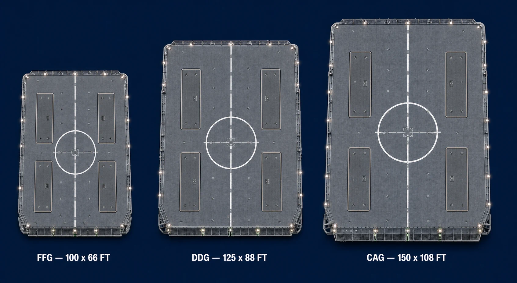
Common flight-deck fit: four paint-free PRIME tops remain at least 15 ft inboard of each deck edge on the 100 ft x 66 ft FFG, 125 ft x 88 ft DDG, and 150 ft x 108 ft CAG deck studies. The dedicated page retains the CAG four-versus-six allocation decision.
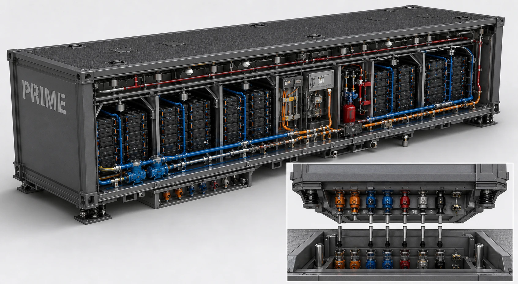
Internal architecture: one 40 ft x 8 ft x 10 ft liftable unit combines its unpainted deck top, isolated battery bays, redundant cooling, protected high-voltage distribution, fire and gas controls, monitoring, and a downward-facing underside plug block. The matching receptor faces upward from the hull-compartment floor.
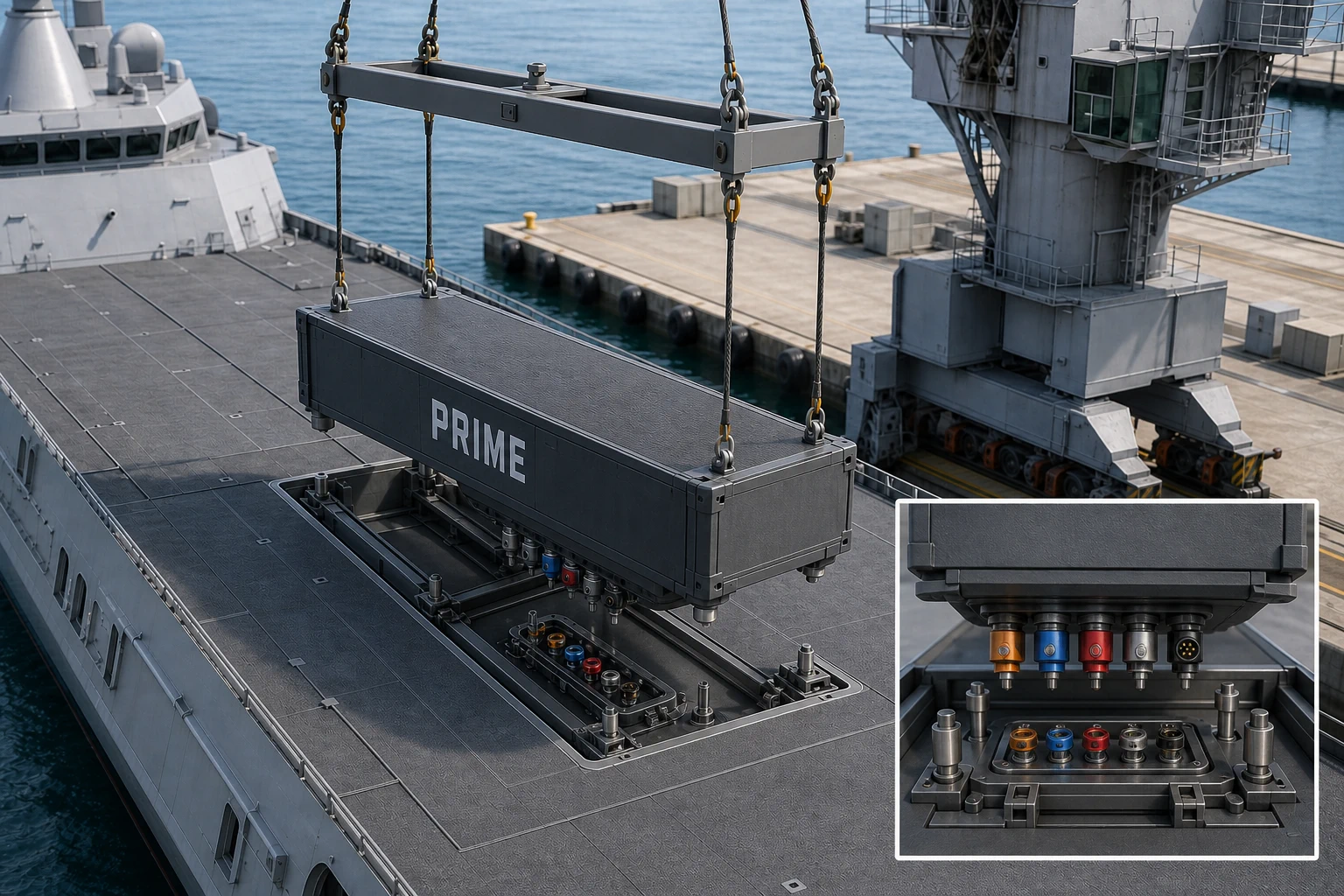
Guided pier exchange: four recessed shackles connect to a rigid spreader; tapered pins and keyed rails align the unit before its downward-facing underside plug block snaps vertically into the upward-facing hull receiver and mechanical locks secure the installation.
What It Is
- Acronym meaning: PRIME = Primary & Reserve Integrated Modular Energy.
- Module rating: 10MW peak-power module in the current fleet canon.
- Class fit: CAG x6 modules, DDG x4 modules, FFG x4 modules.
- Energy reality: a realistic navalized target is approximately 4-6 MWh usable energy per 40-foot module once shipboard hardening, thermal controls, suppression, gas handling, and armored deck-top requirements are included.
- Mission use: silent operations, load smoothing, surge power, emergency backup, and short electric-only tactical mission windows.
- Integration: plug-in self-contained battery modules with hardened flight-deck tops, standardized lift / hook points, fire-suppression access, and crane-removal swap logic for in-port maintenance.
Why We Are Doing It
- Provide reserve energy for silent operations, surge loads, and future high-demand systems.
- Support consistent fleet growth without class-unique power redesigns.
Used Today / What It Counters
- Used today: containerized battery approaches and IPS-derived power controls are already established in fleet/commercial pathways.
- Counters: power shortfalls during high-demand combat loads and degraded-power casualties.
Current Stop Gap
- Containerized lithium-ion baseline tied into existing ship power architectures.
- Ship remains fully operable without PRIME as a hard dependency.
Next Flight Implementation Steps
- Select and certify flight-approved battery chemistry and safety controls.
- Integrate PRIME through AEGIR control logic and test under casualty conditions.
- Field during planned block windows with no unplanned hull changes.
Options and Styles
- Chemistry Options: chemistry-agnostic reserve-energy framework with qualified baseline chemistry per flight.
- Class Allocation Styles: CAG x6, DDG x4, FFG x4 baseline module counts.
- Mission Styles: silent-operations reserve, surge-load support, casualty-power reserve, and electric-only tactical quiet mode.
Mounting and Integration Particulars
- Installed as module sets integrated through AEGIR-managed power distribution.
- The hardened top is the flight deck, not a hatch beneath it; it remains unpainted so modules can be exchanged without class-specific repainting.
- Wells remain at least 15 ft inboard of deck edges to protect the covered-passageway structure below.
- Four recessed lifting shackles, a rigid spreader, tapered guide pins, keyed rails, downward-facing battery plugs, an upward-facing hull-compartment receptor, and positive seating locks govern every crane exchange.
- Treated as modular energy inserts aligned to refit/block insertion discipline.
13. Trinion Naval Gun Family
Open dedicated page for this technology
What It Is
- Family baseline: modernized 10-inch naval artillery concept.
- Heavy baseline: 10"/65 Trinion-H for the CAG, packaged as one complete Gun IWM mated fore-to-aft with one separate Magazine IWM.
- Lite baseline: 10"/45 Trinion-L for the DDG, packaged as one lighter-armored Gun IWM with shorter barrels, reduced machinery weight, and no companion Magazine IWM.
- Both variants retain a triple-barrel turret, three independent breeches and loader channels, and the same 10-inch ammunition family.
- Transitional path: Mk 45 Mod 4 remains baseline until qualification gates are complete.
- Integration model: IWM insertion at refit, not hull redesign.
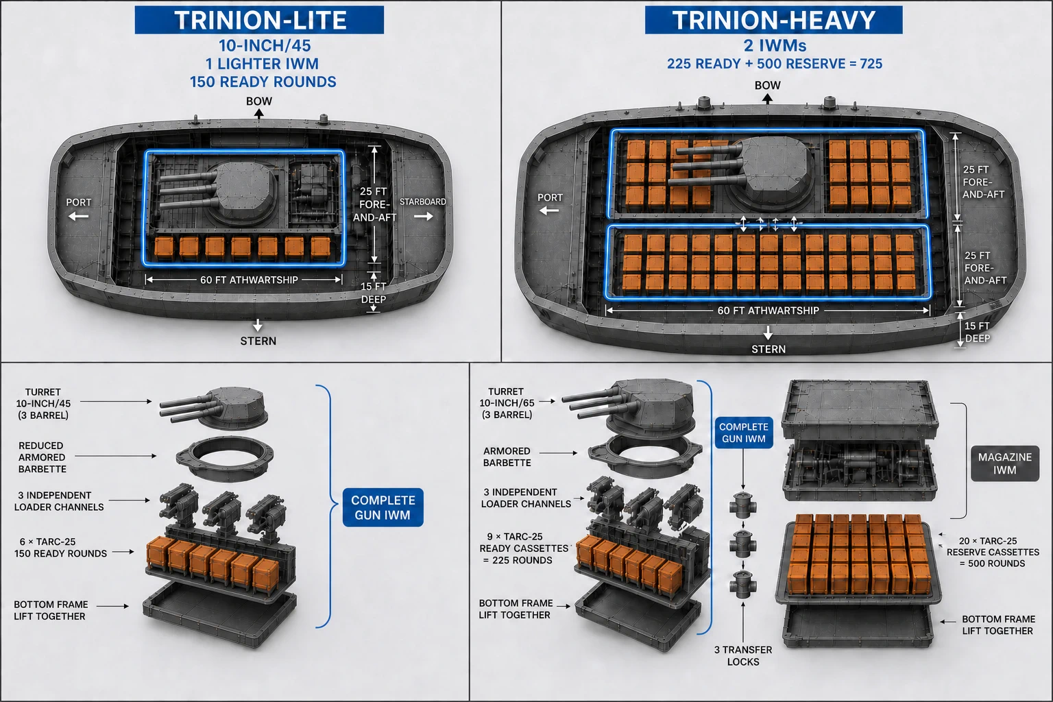
Variant packaging: Trinion-Lite is a single lighter-armored 10"/45 Gun IWM with a planning load of 6 TARC-25 cassettes, or 150 ready rounds. Trinion-Heavy is a 10"/65 Gun IWM with 9 ready cassettes mated to a separate 20-cassette Magazine IWM, providing 225 ready and 500 reserve rounds. The numeric baseline governs where the conceptual rendering shows repeated cassette forms.
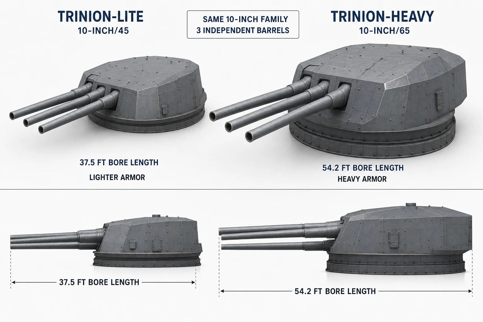
Turret-family scale: the 10"/45 Lite path uses a 37.5 ft bore and reduced armor for the DDG, while the 10"/65 Heavy path uses a 54.2 ft bore and heavier protection for the CAG. Both retain exactly three independently controlled barrels.
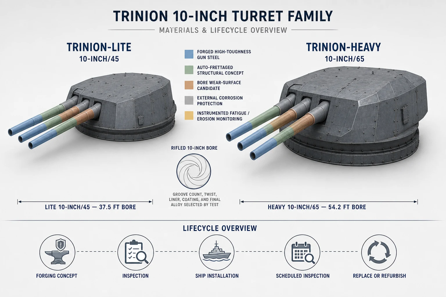
Materials and lifecycle concept: forged high-toughness gun steel, an autofrettaged structural approach, candidate bore wear protection, external corrosion protection, and instrumented fatigue and erosion monitoring define the research direction. Groove count, twist, liner, coating, and final alloy remain qualification-test decisions rather than locked specifications.
Why We Are Doing It
- Increase fleet naval-fire depth with a common gun family across classes.
- Develop programmable or guided defensive gunfire against drone swarms and selected airborne threats, subject to modeling, instrumented testing, and Navy certification.
- Preserve Mk 51 AGS lessons while avoiding a one-off class-specific path.
- Protect CAG identity as a heavy cruiser by retaining large-caliber organic naval fires as a core capability.
- Reduce missile expenditure by using lower-cost gun rounds for missions that do not require missile-class effects.
- Support deterrence signaling: "speak softly, carry a big stick" through visible heavy-gun presence.
Used Today / What It Counters
- Used today: Mk 45 Mod 4 remains the active U.S. Navy baseline while Trinion is validated.
- Counters: surface and shore targets while reducing missile spend for missions that do not require missile-class weapons.
Current Stop Gap
- Mk 45 Mod 4 baseline remains in place until Trinion is fully certified.
Next Flight Implementation Steps
- Complete qualification gates for safety, reliability, and ammunition performance.
- Certify Trinion IWM fit within fleet-standard LCB and interface constraints.
- Insert by block/refit window (no mid-build redesign after first steel cut).
Options and Styles
- Gun Type Options: 10"/65 Trinion-H heavy two-IWM installation for CAG and 10"/45 Trinion-L single-IWM installation for DDG.
- Ammunition Options: LEGACY-AP, FIRE-VEIL HE/frag, IRON-SPEAR sabot AP, IRON-DOME close-in defensive burst research, and DRONE-AHEAD anti-swarm research, with any guided defensive load requiring separate qualification.
- Employment Styles: salvo fire, ripple fire, airburst/swarm intercept, and long-range surface/shore fires.
- Transitional Style: Mk 45 Mod 4 baseline remains active until Trinion qualification and fleet insertion gates are complete.
- Program Packaging: gun and ammunition family are treated as one Trinion new-tech package for qualification, insertion, and lifecycle planning.
Mounting and Integration Particulars
- Primary insertion is through certified IWMs sized to fleet-standard 60 ft x 25 ft x 15 ft LCB constraints.
- Trinion-Lite fits completely inside one IWM: turret, reduced armored barbette, three loaders, controls, and 6 TARC-25 ready cassettes.
- Trinion-Heavy uses two consecutive crosswise IWMs on the centerline: one complete Gun IWM and one Magazine IWM connected through protected transfer locks.
- Selling point: because Trinion is an IWM payload, the mount can be removed at refit and replaced with alternate IWM families (missile, railgun, or future DEW payloads) without hull redesign.
Legacy Systems Moved Into TriSeadon Baseline
These are not counted inside the 11 new systems. They are the fielded, transitional, or legacy-derived systems TriSeadon carries forward so the fleet can build now while the new-tech wave matures.
Two-stage integration rule: a fielded weapon may enter an early hull in its existing Navy-certified legacy mounting arrangement when the corresponding TriSeadon module has not completed engineering and qualification. The weapon moves into the IWM or Cerberus architecture only after its structural, shock, power, cooling, data, fire-control, magazine, maintenance, and safety interfaces pass their required readiness gates. The shipbuilding schedule does not wait for either the final TriSeadon weapon or its interim modular adapter.
Legacy Combat Weapons: Conventional First, Modular Stop Gap Second
- Mk 45 Mod 4: the 5-inch gun may initially use its conventional Navy-certified deck, magazine, handling, and combat-system installation. After the Mk 45 package is engineered and qualified as a complete Integrated Weapon Module, later builds and authorized major refits use the Mk 45 IWM as the modular gun stop gap until a Trinion or other approved successor is ready.
- Mk 41 VLS: early ships may use a conventional Navy-certified Mk 41 launcher installation when required for schedule and missile compatibility. After the launcher, canisters, strike-down and access provisions, structure, exhaust management, fire protection, controls, and magazine interfaces are qualified inside the LCB standard, Mk 41 moves into a certified IWM stop-gap configuration while the preferred Mk 57 PVLS-centered path matures at fleet scale.
- Phalanx, SeaRAM, and HELIOS: these systems may initially retain their existing Navy-certified foundations and ship-specific support arrangements. They transfer to Cerberus positions only after each weapon receives a qualified Cerberus adapter and completes mechanical, electrical, cooling, data, fire-control, shock, firing-arc, maintenance, and safety certification.
- What modular stop gap means: IWM and Cerberus packaging does not make a legacy weapon permanent or automatically compatible. It creates a controlled, replaceable bridge that supplies immediate combat capability while purpose-built TriSeadon guns, launchers, directed-energy weapons, and terminal-defense systems complete development and fleet qualification.
- No schedule hold: failure to complete an interim IWM or Cerberus adapter on time does not delay the hull. The approved conventional legacy installation remains authorized until the modular engineering milestone is achieved and a build or refit receives the certified package.
Transitional Integration Renderings
These are unclassified proposal visualizations of the modular integration paths, not final production drawings or proof of certification.
Mk 45 Mod 4 IWM
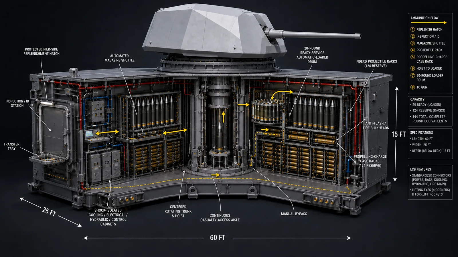
Certified conventional installation first; complete gun-and-magazine IWM after module qualification.
Mk 75 76 mm Gun IWM
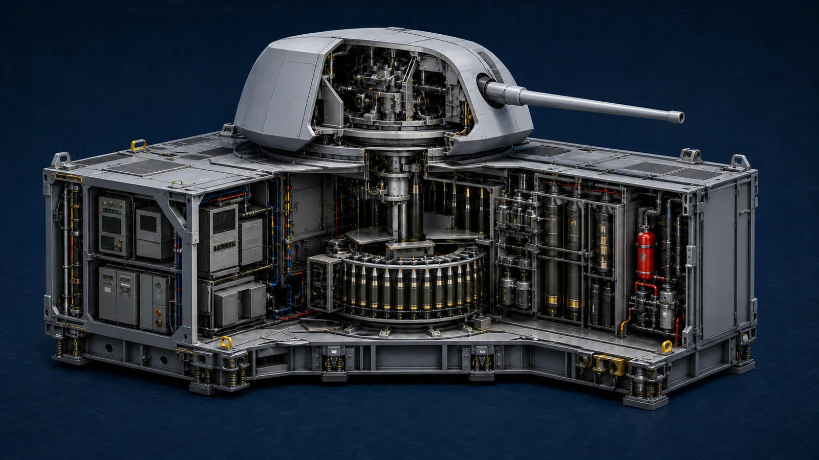
Compact rapid-fire gun, magazine, ammunition handling, controls, and ship-service interfaces engineered as one complete IWM.
Mk 41 VLS IWM
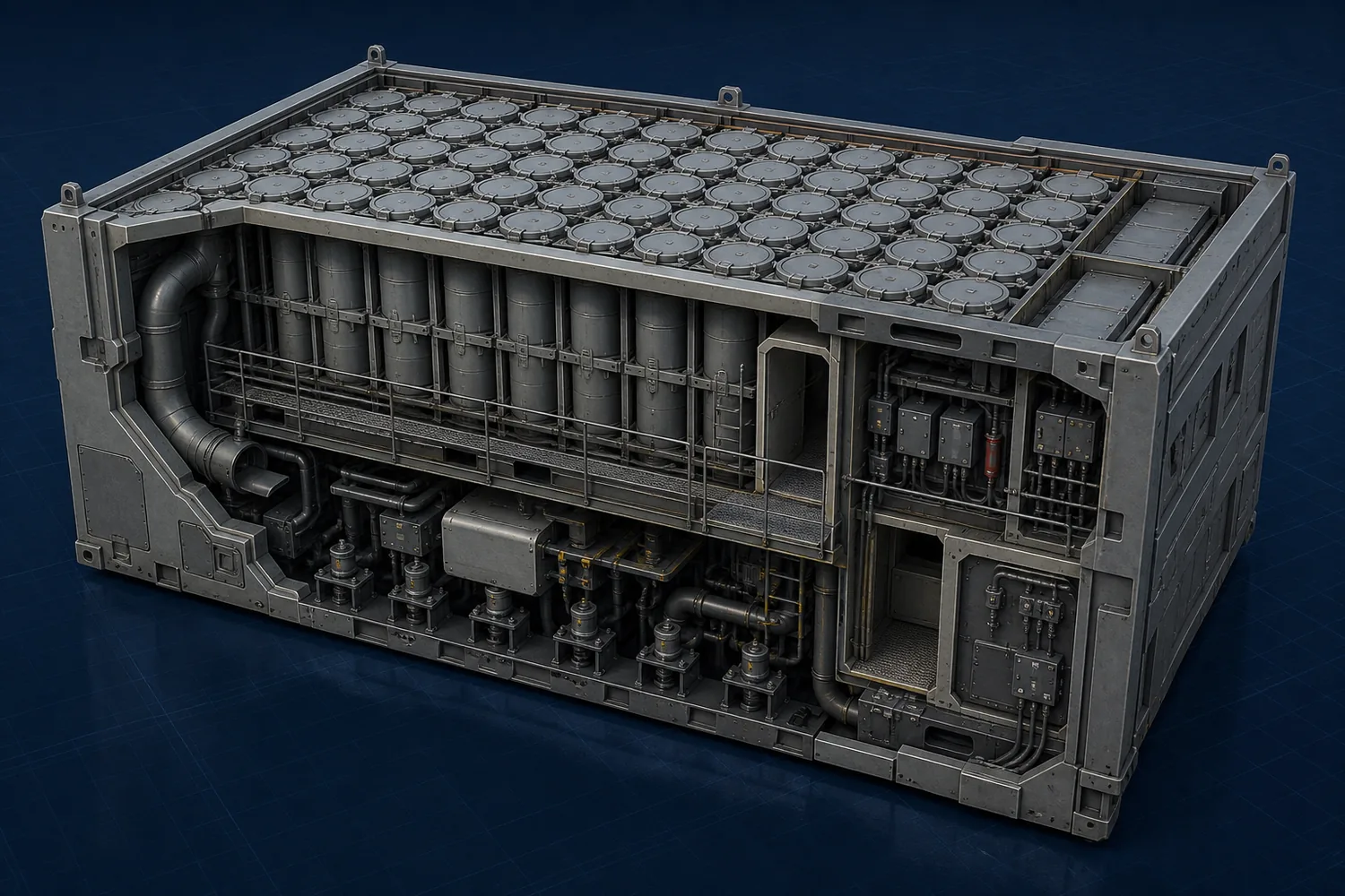
Legacy launcher installation first when required; compatibility IWM after LCB integration qualification.
Phalanx on Cerberus
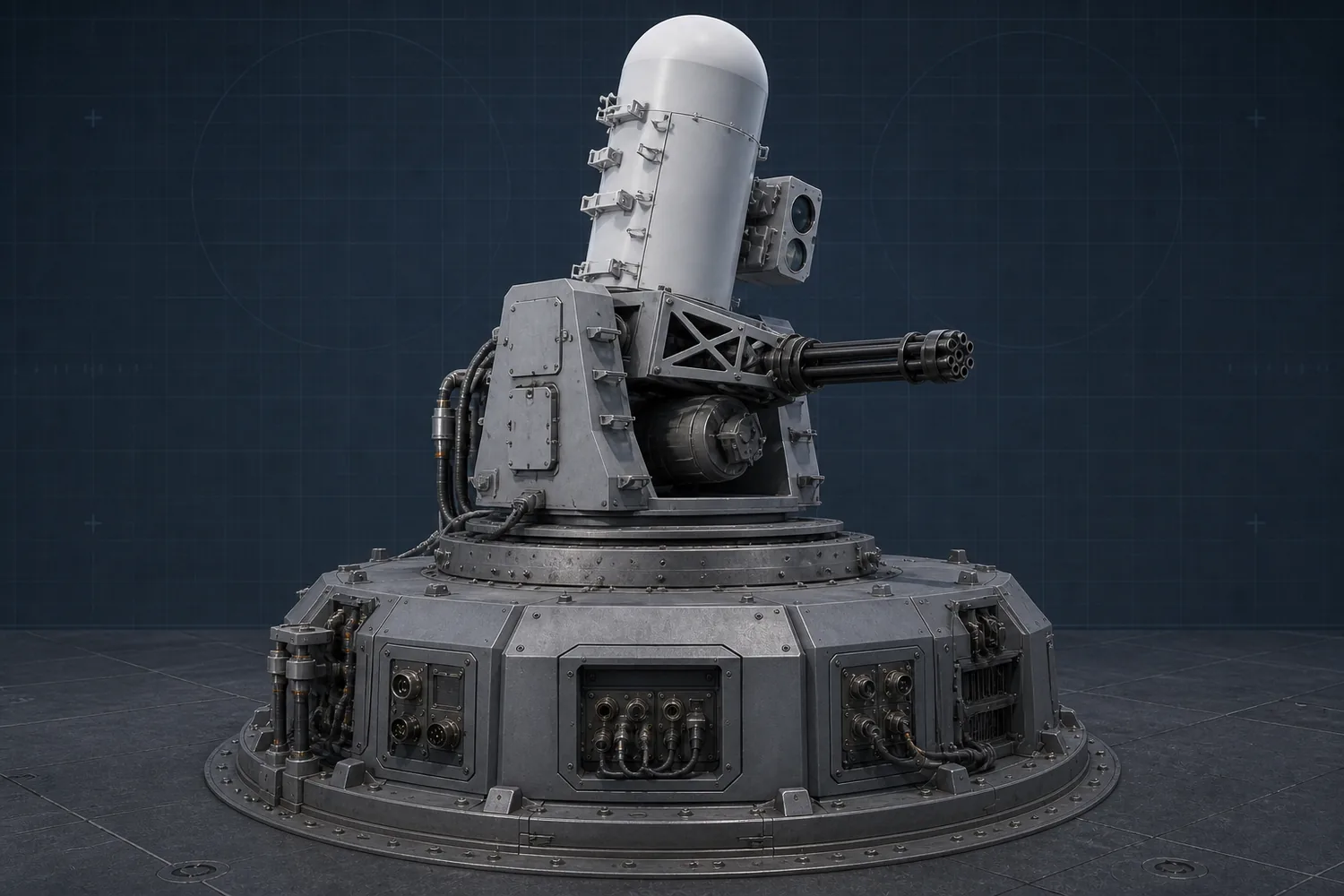
Existing Phalanx foundation first; Cerberus adapter only after interface and firing qualification.
SeaRAM on Cerberus
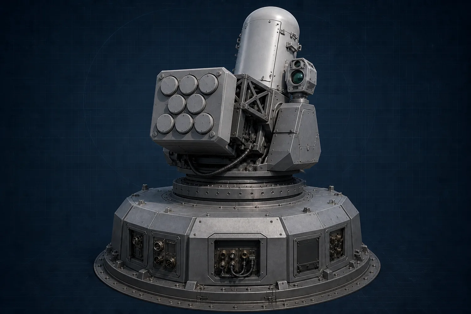
Conceptual adapter arrangement; final launcher geometry remains controlled by the certified SeaRAM shipset.
HELIOS on Cerberus
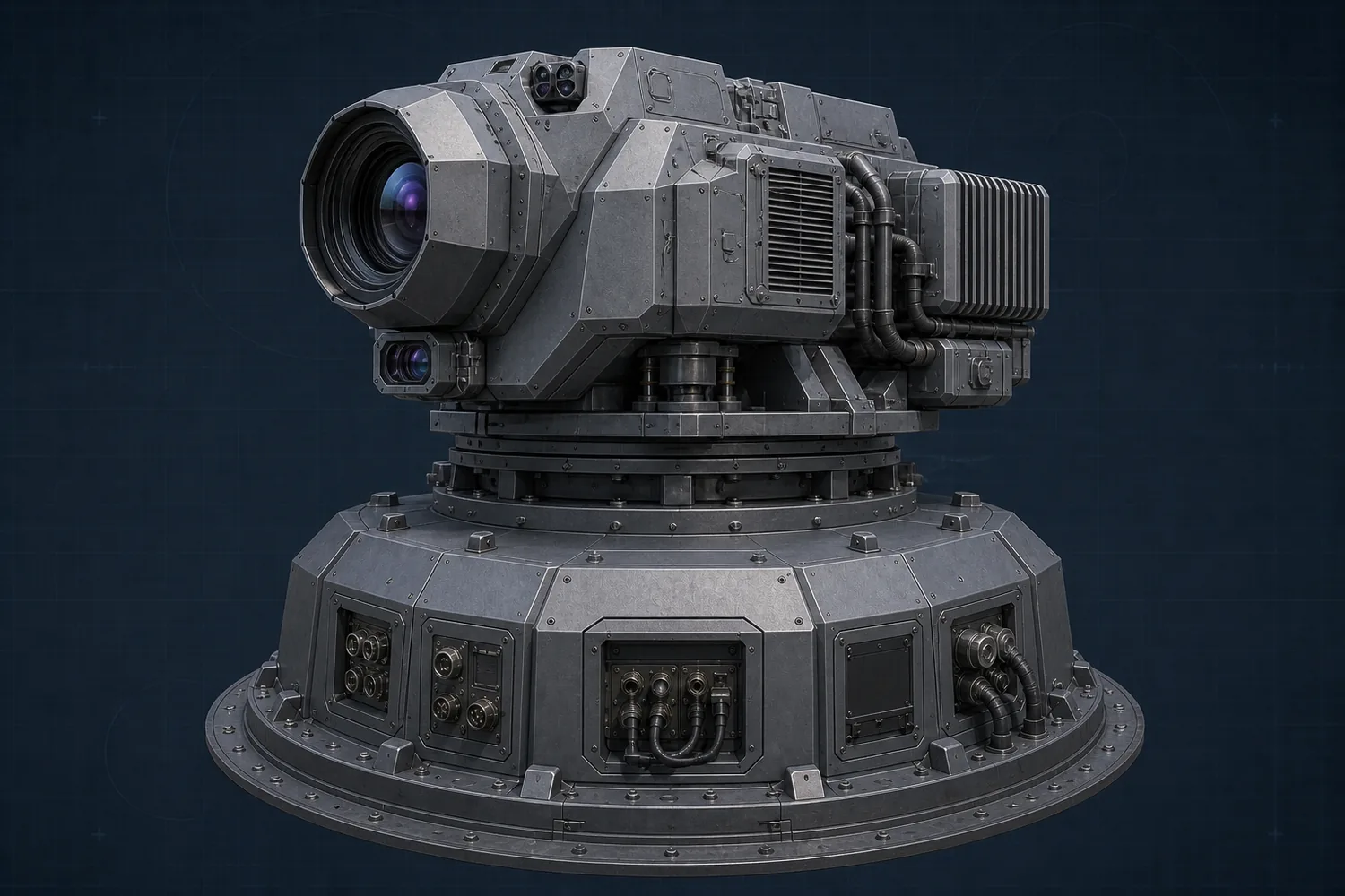
Existing certified installation first; Cerberus integration after power, cooling, optical, and combat-system qualification.
Common Display System (CDS) and CDS-Derived Control Baselines
- Role in TriSeadon: current console and operator-control baseline carried forward until full ONE-Consul transition gates are complete.
- Why it stays: it lets the program field proven control architecture first instead of waiting for the final console environment.
- Transition rule: CDS-family logic remains active as the bridge path while ONE-Consul matures by block and refit.
Power Grid, Electric Propulsion, and GT / DE Power Baseline
- Role in TriSeadon: proven electric-drive and gas-turbine / diesel-electric power logic is carried forward as the current buildable baseline before the full AEGIR and Odyssey end-state is universal.
- What it includes: existing integrated power-grid concepts, electric power to shafts, LM2500+G4 gas-turbine-generator power, and Fairbanks Morse Defense PA6B STC diesel-generator support architecture.
- Fleet standard: every skid, sled, packaged plant, machinery room, and engine room is treated as a USN marine-grade warfighting space with acoustic insulation, vibration isolation, sound damping, and quiet-running treatment as a baseline requirement rather than a class-specific option.
- Transition rule: these systems stay in service as the bridge path until AEGIR-managed tri-source power and certified pod rollout are complete.
LM2500+G4 Turbine Baseline
- TriSeadon role: shipboard gas-turbine-generator package mounted in an acoustically managed, maintainable machinery-room skid/enclosure for sprint power, combat-load support, and high-demand electrical generation.
- Official current engine data: GE Aerospace lists the LM2500+G4 at 47,370 shp / 35,320 kW, with 0.352 lb/shp-hr (214 g/kW-hr) SFC, 205 lb/sec (93 kg/sec) exhaust gas flow, 1,020 degrees F (549 degrees C) exhaust temperature, and 3,600 rpm power turbine speed.
- Packaging logic for TriSeadon: the program treats the LM2500+G4 as a generator-driven power module on a naval skid, not as an exposed standalone turbine. Public GE pages confirm modular maintenance features such as split compressor casing, in-place blade and vane replacement, in-place hot-section maintenance, and external fuel nozzles.
- Acoustic baseline: every LM2500+G4 package is assumed to be mounted in a USN marine-grade ASW sound-damped skid/enclosure with vibration control, access panels, and machinery-room acoustic treatment around it.
- Naval module baseline: GE public naval material confirms the LM2500 family is available in generator-set form and that newer marine modules use improved access, lighter enclosure structures, and better sound attenuation for shipboard use.
- Dimension note: GE's current public LM2500+G4 naval pages do not publish a shipboard skid/module dimension table, so TriSeadon should treat exact machinery-room package dimensions as OEM controlled pending final shipset drawings even though GE states the LM2500, LM2500+, and LM2500+G4 marine modules were shortened to the same family length and footprint for upgrade flexibility.
Fairbanks Morse Defense PA6B STC Diesel Baseline
- TriSeadon role: sled-mounted marine diesel generator package used for economical cruise, hotel load, low-signature operations, and standard 60-month swap-out / rebuild cycling.
- Official current family range: Fairbanks Morse Defense lists the FM PA6B STC generator family at 4,030 kWe (12V), 5,375 kWe (16V), 6,045 kWe (18V), and 6,720 kWe (20V) at 900 rpm, with propulsion-family ratings up to 8,100 kWm at 1,050 rpm.
- TriSeadon rating note: the site's long-standing 8 MW diesel figure should be read as an 8 MW-class program target package derived from the PA6B STC family and installation concept, not as the current public OEM generator-table rating.
- Official engine family geometry: cylinder bore 280 mm, stroke 330 mm, four-stroke cycle, and generator efficiency listed at 96%.
- Official current dimensions: 12V: 5,619 x 2,340 x 3,130 mm, 27.0 metric tons dry. 16V: 6,539 x 2,340 x 3,130 mm, 35.1 metric tons dry. 18V: 7,398 x 2,665 x 3,169 mm, 39.1 metric tons dry. 20V: 7,858 x 2,665 x 3,169 mm, 41.7 metric tons dry.
- Acoustic baseline: every PA6B STC package is assumed to sit on a USN marine-grade ASW sled with acoustic shielding, vibration isolation, and quiet-running treatment, inside machinery spaces that are themselves insulated and padded for low-signature warfighting operation.
- TriSeadon packaging logic: these engines are treated as marine-ASW sled modules with common shipboard hookups, common service geometry, and planned removal through side garage / machinery access paths during standard 60-month refit.
Auxiliary Ship-Service Baseline
- TriSeadon role: the same modular, removable, fleet-standard logic applied to turbines, diesel gens, pods, and batteries also applies to core ship-service hardware such as water makers, air-conditioning plants, chilled-water equipment, pumps, valves, and selected tank packages.
- Packaging doctrine: where practical, these systems are carried as USN-certified skid, sled, or packaged plant units with common hookups, common bolt patterns, common service geometry, and common removal paths rather than class-unique one-off installs.
- Water maker baseline: desalination / freshwater-production plants should be treated as removable packaged machinery-room units sized to the class demand but connected through the same fleet-standard electrical, piping, drainage, and control interfaces.
- HVAC and A/C baseline: chilled-water plants, air-handling units, and machinery-room/environmental-control packages should be standardized around fleet interface rules so they can be upgraded, replaced, or rebuilt without redesigning each hull's service architecture.
- Pumps, valves, and tank systems: TriSeadon should standardize pump families, valve families, actuator/control families, and tank connection geometry as far as mission and class loads allow, so replacements remain inside one DLA-managed support ecosystem instead of separate class-specific parts chains.
- Acoustic service-space rule: all of these skid and packaged support systems are assumed to be USN marine-grade quiet-running units mounted in insulated, padded, and vibration-controlled machinery spaces so the fleet's low-signature requirement applies to support hardware as well as to propulsion hardware.
- Maintenance logic: the objective is to make auxiliary systems behave like planned replaceable ship-service modules. During standard 60-month refit, a failed or obsolete plant should be removable and replaceable by a certified fleet-standard package instead of forcing bespoke depot fabrication.
- DLA effect: once standardized, these support systems become part of the same strategic inventory and rebuild loop as the larger machinery packages, reducing vendor lock and making common service hardware easier to source across all three classes.
Mk 75 76 mm Gun IWM
- Existing system: the Mk 75 is the fielded 76 mm/62-caliber rapid-fire naval gun used by the U.S. Navy and allied fleets.
- TriSeadon package: the weapon enters the fleet as an IWM containing the mount, integrated magazine, ammunition handling, local controls, cooling, fire protection, power conditioning, data interfaces, and maintenance access required for a complete certified installation.
- Mission use: a Mk 75 IWM provides an optional medium-caliber gun for surface defense, patrol, escort, small-craft engagement, warning fire, and other missions where another gun is more appropriate than consuming a larger missile or heavy-gun position.
- Class availability: FFG, DDG, and CAG may receive the package at build or during an authorized drydock major-overhaul/refit when mission demand justifies giving up that LCB/IWM position.
- Certification boundary: common interfaces do not create automatic fit. Each installation still requires class-specific structural, recoil, blast, stability, firing-arc, magazine-safety, combat-system, shock, and environmental certification.
U.S. Navy Mk 75 fact file | Open the complete IWM catalog
Mk 51 AGS and Railgun IWM Development Paths
Mk 51 AGS IWM
- Existing system: the BAE Systems Mk 51 AGS (Advanced Gun System) is a 155 mm, single-barrel, vertically loaded, highly automated gun-and-magazine installation developed for DDG 1000.
- Government-rights gate: TriSeadon does not assume that the government possesses every technical-data and reuse right needed to repackage Mk 51 AGS. The Navy must audit its contract rights, drawings, software, interfaces, tooling, and licensing before selecting the existing design.
- Acquisition alternatives: if rights are sufficient, the Navy may compete an Mk 51 AGS repackaging and modernization effort. If rights are incomplete or the original design is unsuitable, the Navy should acquire the missing rights or issue a performance-based RFP for a functionally equivalent 155 mm naval-gun IWM using government-owned interfaces.
- Physical-fit boundary: the original Mk 51 AGS is larger and deeper than a simple deck gun. A TriSeadon fit may require a deep single LCB, a double-LCB gun-and-magazine installation, or a redesigned Mk 51 AGS family package. FFG, DDG, and CAG retain an integration path, but each fit requires class-specific recoil, structure, weight, center-of-gravity, magazine, handling, blast, stability, and combat-system certification.
- Ammunition competition: the gun is not accepted without an affordable, producible ammunition family. Projectile bodies, guidance options, propelling charges, fuzes, handling equipment, packaging, training rounds, and lifecycle support are competed as separable work packages with common government-controlled interfaces and second-source rights.
- Industrial participation: qualified primes, nontraditional vendors, small businesses, GOCO tenants, and 50-state module-campus suppliers may bid for approved components. Explosives, propellants, warheads, and energetic integration remain restricted to appropriately licensed, secured, and Navy-certified ammunition facilities.
Railgun IWM
- Development status: railgun remains a research and development path, not a fielded TriSeadon weapon or a ship-construction dependency.
- RFP package: the competition covers the mount, barrel and wear management, pulsed-power conditioning, energy storage, cooling, projectile and sabot family, loading and magazine equipment, fire control, electromagnetic compatibility, safety, and maintainability as one certified weapon system.
- Module rule: the objective is a single- or double-LCB Railgun IWM that uses the same government-controlled structural, power, cooling, data, fire-protection, handling, and software interfaces as other IWMs. If the system cannot remain inside those boundaries, it does not force a hull redesign.
- Insertion gate: land-based prototype testing, barrel-life and projectile-cost proof, naval shock and environmental qualification, electromagnetic-effects testing, and at-sea demonstration precede installation on a new flight or an existing ship.
Why the IWM Architecture Matters
The permanent LCB and its common services are built with the ship; the weapon IWM is selected at construction or replaced during a certified drydock major-overhaul/refit availability. This allows Mk 51 AGS, railgun, missile, directed-energy, Trinion, or future systems not yet conceived to compete for the same controlled ship interface without redesigning the hull. Modularity creates an integration pathway, not automatic compatibility: every replacement still requires engineering, safety, combat-system, stability, and operational recertification.
BAE Systems Mk 51 AGS description | Navy Mk 51 AGS major-component description | Open the complete IWM catalog
Mk 57 PVLS / Mk 41 VLS Launch-System Legacy Paths
- Role in TriSeadon: legacy and in-service launcher pathways are retained so missile compatibility exists from the start instead of waiting for the final magazine architecture to mature.
- Baseline carry-forward: Mk 57 PVLS is the primary TriSeadon VLS architecture. Mk 41 VLS may begin in its conventional Navy-certified arrangement and then move into a certified compatibility IWM for missiles available only through the fielded Mk 41 VLS ecosystem.
- Terminology correction: Mk 51 AGS is the designation associated with the Mk 51 AGS gun weapon system, not a TriSeadon VLS. It belongs in the Mk 51 AGS family IWM path above.
- Transition rule: conventional Mk 41 installation remains authorized until the Mk 41 IWM engineering gates are passed; the certified Mk 41 IWM then remains the modular compatibility stop gap until the preferred TriSeadon magazine path is fully certified, supplied, and fielded at scale.
APM Bridge Alignment
- Role in TriSeadon: APM is carried as a current bridge-aligned strike path rather than treated as an all-new isolated invention.
- Why it stays: it lets TriSeadon tap an active modernization lane for larger payload and hypersonic strike without delaying the fleet.
- Transition rule: APM remains part of the baseline strike bridge while the broader TriSeadon combat architecture grows around it.
Fleet TriSeadon Baseline
Decision Brief | Baseline Lock Sheet
Source and Technology Baselines (Common to CAG, DDG, FFG)
- Semi-common architecture baseline: shared combat-system logic, power philosophy, interfaces, module standards, and selected common parts across all three classes.
- Standard layout rule: the three classes use the same fleet-standard wiring architecture, cooling hookups, exhaust-service standards, bolt patterns, plugs, and core machinery-service layout wherever the common system family applies.
- Class scale baseline: FFG about 500 ft x 66 ft, DDG about 650 ft x 88 ft, and CAG about 800 ft x 108 ft.
- Hull-role split: FFG is shaped for ASW quieting, DDG for speed and maneuver, and CAG for stability, deck utility, and command/air operations.
- Common command architecture: Bridge, CIC, ATC, and DMC cross-wired with redundant controls.
- Integrated modular design: drydock LCB integration and in-port ISO mission module swaps.
- Integrated power and propulsion model: turbines, diesels, and battery systems with growth margin.
- Maintenance logic: common layout and common service standards are used so modules, machinery, mounts, and support equipment can be removed, replaced, and reinstalled with the same fleet-standard connection logic across FFG, DDG, and CAG.
- Single-fuel fleet baseline: ships, helicopters, boats, vehicles, turbines, generators, and support equipment are standardized on JP-5 wherever practicable so the fleet trains, stores, and refuels against one naval fuel standard.
- Standardized weapons/mount interfaces for rapid tech insertion across classes.
- Technology discipline rule: no hull flight or revision cycle takes more than 3 major new technologies.
- Common undersea-vehicle baseline: every class carries SeaFox mine-identification, training, and neutralization vehicles; reusable very-small UUVs for confined-water inspection and reconnaissance; and small UUV or Seaglider-family vehicles for survey, ocean sensing, mine search, acoustic collection, and distributed ASW support. Fleet-common power, charging, data, payload, handling, maintenance, and DMC interfaces allow vehicle models to change without redesigning the ship.
- UUV/USV expansion standard: each hull reserves physical and electrical margin for future unmanned growth, including storage, workshops, battery charging, fuel service where required, mission-data links, payload preparation, handling, launch and recovery, and DMC operator capacity. New UUV and USV systems enter through fleet-standard interfaces or mission-specific IMM, ISO, and LCB packages as they mature and receive certification.
- Organic boat and recovery standard: every class has independent enclosed port and starboard garages, each carrying a fleet-standard 7-meter multipurpose RHIB and an integrated side-launch/recovery system. The common RHIB replaces separate motor-whaleboat and captain's-gig hulls; CAG adds the protected TriSeadon Admiral's Launch (TAL), a 16-meter-class RCB/CB90 derivative with a separate heavy-craft handling system. Larger or specialized boats remain modular. Open boat-system detail.
Force Multiplier Doctrine (How the Fleet Compounds Combat Power)
TriSeadon doctrine is non-linear: each ship is self-sufficient alone, but combined effect scales faster than hull count because sensors, shooters, magazines, and mission modules operate as one networked system.
- Preferred operating model: a TriSeadon Task Group normally centers on 1 CAG, 2 DDGs, 3 FFGs, and 1 supporting SSN, with a second SSN or other forces added for higher-threat missions. This is the fleet's best-effect planning baseline, not a rigid formation; commanders tailor, divide, or reinforce it as the mission requires. Open TTG doctrine.
- CAG provides flagship command, the Marine quick-reaction force, assault aviation, and afloat medical sustainment for embassy evacuation, reinforcement, shore extraction, and crisis-response operations.
- DDG provides air/missile shield functions with mission-based SOF integration and distributed strike support.
- FFG provides ASW-forward screening with 2 mission-configured MH-60R/S helicopters, a modular MQ-19 Aerosonde, MQ-27 ScanEagle, RQ-21 Blackjack-compatible, or follow-on UAS detachment, UDT pathways, and undersea/littoral sensing dominance; ASW deployments normally favor MH-60R.
- Shared sensor web: SPY-6, EO/IR, EW, helo sensors, UxV feeds, and sonobuoy fields from multiple ships are fused into one engagement picture.
- Shared shooter logic: Aegis/CEC/CANES allows the best-positioned shooter to engage from across the formation instead of each ship fighting only its own radar horizon.
- Shared magazine effect: Mk 57 PVLS/APM missiles, Trinion or Mk 45 Mod 4 naval fires, RAM/CIWS/Cerberus layers, EW effects, chaff, decoys, armor, and module payloads are employed as a coordinated group inventory; taken together, the three-hull family is intended to field the deepest combined missile battery and the heaviest layered defensive battery in the concept.
- Distributed ASW mass: multiple MH-60 sorties, MQ-19 Aerosonde, MQ-27 ScanEagle, RQ-21 Blackjack-compatible and future VTOL UAVs, UUV/USV packages, and cross-ship sonobuoy prosecution create wider search coverage and faster kill chains than single-ship ASW.
- Current small-UAS baseline: TriSeadon prioritizes the MQ-19 Aerosonde and MQ-27 ScanEagle families now used in Navy and Marine Corps shipboard ISR services. RQ-21 Blackjack interfaces are retained as a compatible modular pathway rather than a guaranteed standing detachment. MQ-8 Fire Scout is not assigned in the baseline, but common deck, control, data, fueling, and maintenance interfaces preserve a future rotary-wing UAS option if the Navy reinvests and certifies it. Open the NAVAIR small-UAS program update.
- Module compounding: IWM/IMM/ISO packages on different hulls can be mixed per mission so one formation carries strike, air defense, ASW, EW, drone defense, and medical support simultaneously.
- Practical meaning: additional ships add overlapping capability and cross-support, not just more hulls.
- ASuW kill chain: FFG scouts and develops contact, DDG screens the group and adds fast missile or escort fires, and CAG commands the strike and commits the deepest heavy surface or shore-bombardment magazine.
Three Classes and Designations
Each class has a primary warfare role, but all three operate inside one integrated TriSeadon combat architecture.
- FFG (Guided-Missile Frigate): ASW-forward escort and sea-lane control specialist, optimized for undersea screening and distributed sensing, with configurable littoral-control lead mission sets and enough combat depth to fight at Burke-destroyer seriousness rather than as a light escort.
- DDG (Guided-Missile Destroyer): air and missile defense backbone that protects the formation, extends strike/network reach, and is intended to overmatch any conventional surface combatant it engages.
- CAG (Guided-Missile Heavy Cruiser): CAG uses the historical hull-symbol logic of CA for heavy cruiser plus G for guided missile. It is the flagship command-and-response class for surface war, naval gunfire, missile strike, shore insertion, quick-reaction-force operations, and high-capacity theater coordination.
- Common fleet point: TriSeadon proposes high-capacity missile batteries, the return of major naval guns, a required multi-layer Cerberus terminal-defense fit on every class, full EW and decoy coverage, survivability armor discipline, and UAV, USV, and UUV integration across the fleet. Final performance depends on system qualification and ship integration.
Designation purpose: mission emphasis without isolation. Every hull remains interoperable and contributes to fleet-level force multiplication.
Production lock: Build Guided-Missile Frigates (FFG) first, Guided-Missile Heavy Cruisers (CAG) second, and Guided-Missile Destroyers (DDG) third. This order addresses what the U.S. Navy needs today: restore frigate and ASW escort capacity first, replace lost cruiser command-and-strike capacity second, and introduce TriSeadon destroyers third as legacy destroyers age out.
Named Combat-System Baseline
This is the named TriSeadon baseline as it stands now. It lists the real system names the concept is anchored to, plus the TriSeadon-specific growth rules where the program goes beyond today's fleet.
FFG | Named Radar, Sonar, EW, Aviation-Control, Torpedo, and Decoy Stack
- Primary combat radar: AN/SPY-6(V)3F.
- High-resolution fire-control layer: X-band SPY-6 variant tied to Aegis Baseline 10.
- Low-altitude and horizon radar: AN/SPQ-9B.
- Close-water and navigation radar: NGSSR baseline, with SPS-73-class logic only as bridge legacy language.
- Passive and aviation support sensors: IRST21 or SPEIR EO/IR, LIDAR, IFF, TACAN.
- ATC and recovery layer: close-range air-search and recovery radar support, TACAN, IFF, deck-landing aids, and UAV traffic-management tools for 2 mission-configured MH-60 helicopters and MQ-19, MQ-27, RQ-21-compatible, or follow-on scout-drone operations.
- Hull and towed sonar stack: AN/SQS-60 mid-frequency hull sonar, AN/SQS-61 high-frequency hull sonar, AN/SQR-20 multifunction towed array, with CAPTAS-4-equivalent variable-depth sonar path in TriSeadon language.
- EW and SIGINT: AN/SLQ-32(V)6 SEWIP, with counter-UAS and ISO EW growth on top.
- Ship torpedo delivery: Mk 32 Surface Vessel Torpedo Tubes firing Mk 54 lightweight torpedoes.
- Standoff ASW weapon: RUM-139 VL-ASROC carrying Mk 54 VLA logic through the VLS family.
- Close-in defense: Mk 15 Phalanx CIWS or Cerberus gun fit, RAM or SeaRAM-type fit through Cerberus, HELIOS/ODIN-class DEW or dazzler growth.
- Cerberus baseline count: 3 mounts minimum, preserving a gun, missile, and DEW or dazzler layer on the hull at all times.
- Soft-kill and decoys: Mk 53 Nulka active decoy and Mk 36 SRBOC chaff/decoy logic.
- Unmanned and anti-drone layer: UAV and USV operations plus SeaFox, reusable very-small UUV, and small UUV/Seaglider-family systems are tied to counter-UAS defense, mine protection, inspection, survey, littoral reconnaissance, and local air/surface/undersea surveillance as part of the base combat system.
- Armor and survivability: armor and fragmentation protection are built in as part of the shared survivability rule, not left as an afterthought.
DDG | Named Radar, Sonar, EW, Aviation-Control, Torpedo, and Decoy Stack
- Primary combat radar: AN/SPY-6(V)1.
- High-resolution fire-control layer: X-band SPY-6 variant tied to Aegis Baseline 10 for terminal tracking and engagement support.
- Low-altitude and horizon radar: AN/SPQ-9B.
- Close-water and navigation radar: NGSSR baseline.
- Passive and aviation support sensors: IRST21 or SPEIR EO/IR, IFF, TACAN.
- ATC and recovery layer: escort-scale close-range air-search and recovery radar support, TACAN, IFF, deck-landing aids, and UAV traffic-management tools for 2 mission-configured MH-60 helicopters and MQ-19, MQ-27, RQ-21-compatible, or follow-on embarked drones.
- Hull and towed sonar stack: SQQ-90-family logic centered on AN/SQS-60, AN/SQS-61, and AN/SQR-20, with VDS/towed-array mission emphasis in TriSeadon doctrine.
- EW and SIGINT: AN/SLQ-32(V)7 SEWIP Block III and SSEE-F SIGINT/ELINT.
- Ship torpedo delivery: Mk 32 Surface Vessel Torpedo Tubes firing Mk 54 lightweight torpedoes.
- Standoff ASW weapon: RUM-139 VL-ASROC carrying Mk 54 VLA logic through the VLS family.
- Close-in defense: Mk 15 Phalanx CIWS or Cerberus gun fit, RAM or SeaRAM-type launchers through Cerberus, HELIOS/ODIN-class DEW or dazzler layer.
- Cerberus baseline count: 5 mounts in current planning, giving the class denser anti-drone, anti-missile, and close-surface coverage than a single-CIWS destroyer layout.
- Soft-kill and decoys: Mk 53 Nulka and Mk 36 SRBOC, coordinated with SEWIP and fleet air-defense doctrine.
- Unmanned and anti-drone layer: UAV and USV control plus SeaFox, reusable very-small UUV, and small UUV/Seaglider-family operations are part of the escort combat system, tied directly into mine protection, inspection, scouting, ASW geometry, anti-drone, and off-axis targeting workflows.
- Armor and survivability: armor and fragmentation protection are integrated into the design baseline to support missile-war, drone-war, and close-littoral survivability.
CAG | Named Radar, Sonar, EW, Aviation-Control, Torpedo, and Decoy Stack
- Primary combat radar: AN/SPY-6(V)4.
- High-resolution fire-control layer: X-band SPY-6 variant tied to Aegis Baseline 10, scaled for the largest battle-management and terminal-defense burden.
- Low-altitude and horizon radar: AN/SPQ-9B, carried in denser quantity across the hull.
- Close-water and navigation radar: dual NGSSR logic for complex flight-deck and close-ship control environments.
- Passive and aviation support sensors: IRST21 or SPEIR EO/IR, LIDAR, IFF, TACAN, and flagship-grade aviation and drone traffic-management support.
- ATC and recovery layer: dedicated close-range air-search and recovery radar support, TACAN, IFF, deck-landing aids, and UAV traffic-management tools sized for mixed Venom, Viper, 3 MH-60, MQ-19, MQ-27, RQ-21-compatible, and other drone operations at the same time.
- Hull and towed sonar stack: SQQ-90-family logic centered on AN/SQS-60, AN/SQS-61, and AN/SQR-20, used here as an aviation-heavy and command-heavy ASW multiplier rather than the quiet primary hunter role of the FFG.
- EW and SIGINT: AN/SLQ-32(V)7 SEWIP Block III, SSEE-F SIGINT/ELINT, and deeper flagship EW coordination margin.
- Ship torpedo delivery: Mk 32 Surface Vessel Torpedo Tubes firing Mk 54 lightweight torpedoes.
- Standoff ASW weapon: RUM-139 VL-ASROC carrying Mk 54 VLA logic through the VLS family.
- Close-in defense: Mk 15 Phalanx CIWS or Cerberus gun fit, RAM or SeaRAM-compatible launchers, HELIOS/ODIN-class DEW or dazzler layer, and heavier terminal-defense density than the smaller classes.
- Cerberus baseline count: 8 mounts in current planning, giving the class the densest terminal-defense belt in the fleet.
- Soft-kill and decoys: Mk 53 Nulka and Mk 36 SRBOC, integrated into flagship battle-management and layered survivability doctrine.
- Unmanned and anti-drone layer: UAV and USV operations plus SeaFox, reusable very-small UUV, and small UUV/Seaglider-family systems are part of the flagship command picture, supporting mine protection, inspection, scouting, distributed ASW, strike support, recovery control, and layered anti-drone defense.
- Armor and survivability: armor and fragmentation protection are carried as a fleet rule here as well, with the largest margin for damage tolerance in the class.
What Each Class Does in Real Operations
FFG | Anti-Submarine Warfare and Sea-Lane Security
FFG is the fleet's ASW-focused escort and distributed-coverage class. Its combat-system capacity and layered defenses are intended to support independent blue-water operations as well as task-group screening.
- Primary mission: anti-submarine warfare lead ship for convoy, carrier, and amphibious screening.
- Configurable primary mission set: littoral control for ports, channels, and bays against green-water threats.
- Baseline combat battery: 64 Mk 57 PVLS cells with one forward Mk 45 Mod 4 gun or future Trinion-aligned heavy-fire option by block decision.
- Design objective: provide destroyer-grade sensing, self-defense, endurance, and damage tolerance while preserving acoustic performance as the governing ASW requirement.
- Core enablers: SQQ-90-family undersea warfare suite, SQR-20 MFTA, variable-depth sonar path, MH-60R aviation, UUV/UAV/USV-enabled sensing and prosecution, and a low-speed electric-only quiet mode enabled by PRIME reserve modules for reduced acoustic signature.
- Detachment model: permanent UDT support plus 2 mission-configured MH-60R/S helicopters and a modular MQ-19 Aerosonde, MQ-27 ScanEagle, RQ-21 Blackjack-compatible, or follow-on UAS detachment; ASW deployments normally favor MH-60R.
- Littoral package: mine and counter-mine workflows, UDT operations, swift-boat support, and coordinated UUV/UAV/USV control for defend-clear-hold operations.
- Force multiplier function: extends detection and tracking range for the DDG/CAG team, shares passive bearings and sonobuoy fields across the formation, and denies submarine freedom of movement in contested littorals.
- Shared shooter rule: if the DDG or CAG has better geometry, they can fire ASROC, launch torpedoes, send an MH-60R drop, or lay more sonobuoys using the FFG's track and localization picture.
DDG | Air and Missile Defense, Strike Support, and Maritime Operations
DDG is the fleet's primary air- and missile-defense node, with precision-strike capacity, mission-based maritime detachments, and distributed sensor-and-shooter support.
- Primary mission: anti-air, anti-missile, anti-drone, and layered terminal defense with over-the-horizon cueing.
- Baseline combat battery: 128 Mk 57 PVLS cells with one forward Mk 45 Mod 4 gun and a heavier close-in Cerberus belt than current single-CIWS destroyer practice.
- Core AAW enablers: SPY-6 family main radar, Aegis Baseline 10, X-band SPY-6 variant for high-resolution fire-control and terminal tracking, CEC, CANES, Link-16/22, JADC2, SEWIP Block III, IRST or SPEIR EO/IR, and layered close-in defensive screens.
- Detachment model: every DDG carries one mission-based maritime operations detachment selected from NSW/SEAL, SWCC, VBSS, LEDET, or sniper-team elements based on tasking.
- Aviation support: 2 mission-configured MH-60R/S helicopters and a modular MQ-19 Aerosonde, MQ-27 ScanEagle, RQ-21 Blackjack-compatible, or follow-on UAS detachment, integrated with UAV/USV/UUV tasking for layered maritime surveillance, SAR, terminal cueing, drone defense, and engagement support.
- Strike profile: APM magazines support hypersonic strike payloads; any future counter-hypersonic interceptor load requires Navy certification, launcher selection, and ship-integration approval.
- Surface-warfare objective: achieve engagement advantage through magazine depth, integrated fire control, layered terminal defense, off-board targeting, and cooperative sensor data from the task group.
- Force multiplier function: protects ASW maneuver space for FFG, shields CAG command node, and serves as the primary fleet shooter against aircraft, cruise missiles, ballistic threats, drone swarms, and fast raid threats.
- Support role from other classes: the FFG and CAG extend the DDG's air picture with SPY-6 tracks, passive EO or IR cues, EW sensing, UAV or drone-swarm scouting, off-axis geometry, and extra missile or terminal-defense capacity.
CAG | Fleet Command, Surface Warfare, and Crisis Response
CAG is the fleet flagship and heavy surface combatant, providing command-and-control capacity for surface warfare, shore insertion, task-group battle management, aviation, and embarked medical support.
- Primary mission: fleet command and control, surface action, shore insertion support, and theater-level coordination with dedicated flag and command spaces.
- USMC aviation detachment: 2 AH-1Z Viper attack helicopters and 2 UH-1Y Venom utility helicopters provide armed escort, reconnaissance, insertion, extraction, and direct support for the embarked QRF.
- USN aviation detachment: 3 mission-configured MH-60R/S helicopters support ASW, ASuW, SAR, medevac, command transport, recovery, and task-group logistics.
- Hangar and unmanned baseline: 5 enclosed hangars comprise shared Viper and Venom hangars plus 3 individual MH-60 hangars. Integrated aviation workshop and mission-support spaces serve MQ-19 Aerosonde, MQ-27 ScanEagle, RQ-21 Blackjack-compatible, and follow-on VTOL or expeditionary UAV packages without requiring a sixth full hangar.
- Medical and evacuation capability: the embarked medical center supports emergency care, trauma stabilization, surgery, recovery, imaging, diver medicine, and transfer to higher-echelon care when required.
- Combat profile: 200 Mk 57 PVLS cells, APM capacity, and the Trinion heavy-gun architecture provide layered air defense, anti-surface warfare, strike, and sustained naval surface-fire support.
- Design objective: combine flagship command capacity, magazine depth, naval gunfire, aviation support, and survivability margin in a heavy surface combatant configured for task-group command and shore-insertion support.
- Force-multiplier role: sonar and UxV integration extends the DDG/FFG ASW network while CAG provides additional command authority, battle-management depth, and extra radar, EW, aviation, and missile capacity behind the DDG's main AAW screen.
- ASuW role: primary heavy surface-action, ship-killer, and shore-bombardment hull, using its deeper magazine, heavier fires, aviation, and command architecture to coordinate the fleet's surface fight.
Class Technical Profiles
Click each class for mission, dimensions, sensors/combat systems, weapons, and module configuration.
CAG: Guided-Missile Heavy Cruiser
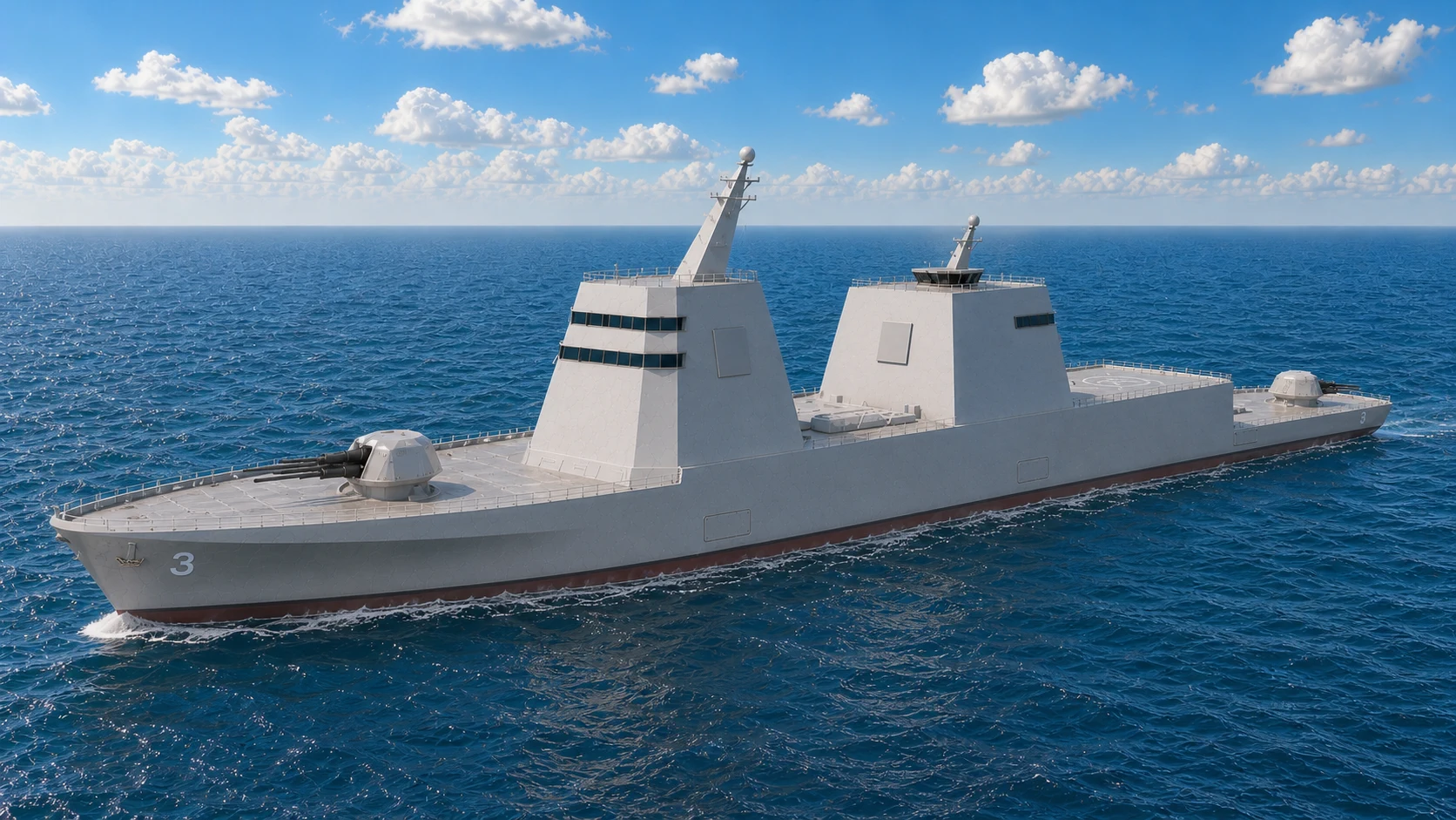
Current CAG-3 visual baseline with locked vertical geometry and aft-aligned ATC.
Mission and Role
Flagship for surface action groups, high-capacity command-and-control node, and heavy fires leader centered on surface war and shore-insertion support.
Designation: Guided-Missile Heavy Cruiser is the formal TriSeadon class name. “Heavy cruiser gunship” describes its major-gun and surface-strike role, but does not replace the broader designation.
Open USNR Medical/Hospital Alternate Hull
Key Dimensions and Performance
- Length 800 ft, beam 108 ft, draft 30 ft, displacement about 32,000 tons.
- The 30-ft figure remains the hull-design draft target; overall navigational draft with the enlarged Odyssey units remains a naval-architecture output.
- Growth envelope: 35,000 tons is an intermediate BBG-oriented objective study case inside the conditional 38,400-ton 20 percent limit. Added displacement is not free payload and requires complete weight, stability, structure, draft, freeboard, seakeeping, propulsion, speed, and endurance validation.
- Vertical geometry: 80-ft forward superstructure including bridge and flag bridge; 60-ft aft aviation superstructure with a 30-ft clear hangar and two 15-ft aviation-support levels. The 40-ft-wide ATC is centered on the 80-ft roof, aligned with the aft bulkhead, and additional to the 60-ft aft-block height.
- Longitudinal arrangement: 220 ft forward weapons section, 280 ft combined superstructure and hangars, 150 ft x 100 ft flight deck at the 01 level, and 150 ft lower main-deck stern section.
- Crew: 450-500 full fighting complement, with automation used to cut wasted labor rather than to strip the ship below proper watchstanding and maintenance levels.
- Berthing capacity: 580, allowing surge staffing, flag staff, diplomatic support, trainees, medical augmentation, and crisis-response embarkation above normal fighting complement.
- Hull scale intent: heavy-cruiser command ship in the battlecruiser/pocket-battleship size class.
- Propulsion set includes four fully azimuthing Odyssey pods rated at 25MW continuous and 27MW short-duration objective each, four LM2500+G4 gas-turbine generators at 35MW each, eight 8MW-class Fairbanks Morse Defense PA6B STC diesel-generator packages, and six 10MW peak PRIME battery modules.
- Speed profile: the current powering estimate is about 29.5 kts at full continuous pod output and about 30 kts at the short-duration objective rating. Final speed requires model-basin, propulsion, cavitation, and resistance validation. Diesel-dominant operation remains about 18 kts, with battery-only operation reserved for short-duration low-speed tactical quiet-mode windows.
- Flight-start note: first 2-3 CAG hulls may be built with shaft/rudder propulsion if Odyssey is not yet approved at build gate.
- Refit option note: if early CAG shaft/rudder hulls are not selected for Odyssey conversion, they may be reassigned to full medical-center conversion during a major refit.
Ideal CAG Hull Design
- Ideal hull concept: the CAG is a large conventional blue-water heavy-cruiser hull built for stability, command volume, flight operations, heavy weapon support, and long-range endurance rather than speed-first geometry.
- Bow form: long bulbous bow and fine flared entry sized for large-ship efficiency, reduced pitching and slamming, and better reserve buoyancy forward when operating a heavy command-and-strike load in rough seas.
- Mid-body form: very broad, high-freeboard monohull with large waterplane area, deep internal subdivision, and enough beam and deck area to support command spaces, aviation functions, medical support, large magazines, and heavy combat-system growth.
- Underwater body: deep centerline keel, strong lower-hull flare out toward the bilge and outer-keel regions, and bilge keels for roll damping, all tuned to keep the ship steady for sensors, weapons, helicopters, and command work in higher sea states.
- Stern form: conventional cruiser-scale stern with spoon-shaped recessed pod-mount sections aft so the four Odyssey pods receive clean flow while the ship preserves buoyancy aft, long-range efficiency, and stable stern behavior.
- Why these features fit the class: the CAG needs the steadiest platform in the family, so it carries the largest waterplane, the strongest reserve buoyancy, the heaviest roll-damping bias, and the fullest stable mid-body to support flight operations, command spaces, and heavy weapons in rougher seas.
- Design priority: the CAG should look advanced because it is large, clean, stable, and purpose-built, not because it uses exotic hull geometry below the waterline.
Energy and Propulsion Architecture
- Three energy systems: 8MW-class Fairbanks Morse Defense PA6B STC diesel generation for economical cruise, station keeping, and hotel load, LM2500+G4 gas-turbine generation for high-speed combat power and sprint transit, and 10MW peak PRIME battery reserve for tactical quiet mode, surge support, ride-through reserve, and peak-load smoothing.
- Combat-power logic: sensors, command systems, EW, aviation support, DEW, and propulsion all compete on the same survivable grid rather than on isolated machinery lines.
- Baseline propulsion path: Odyssey pod architecture is the target end state; shaft/rudder is the acceptable early-flight fallback if pod readiness lags build schedule.
- Future growth path: larger battery reserves, improved pod hardening, stronger DEW cooling margin, and higher-output power routing are all intended block-upgrade candidates.
Sensors and Combat Systems
- AN/SPY-6(V)4 AESA radar with Aegis Baseline 10 and an X-band SPY-6 variant for high-resolution fire-control and terminal tracking, sized with growth margin for later SPY and fire-control upgrades.
- AN/SPQ-9B, NGSSR close-water navigation/surface radar layer, IRST21/SPEIR EO/IR, and LIDAR/IFF/TACAN suite.
- AN/SLQ-32(V)7 SEWIP Block III and SSEE-F SIGINT/ELINT, with additional flagship battle-management margin for theater EW coordination, off-board cueing, and aviation-linked spectrum support.
- Aegis Baseline 10 with CEC, CANES, Link-16/22, JADC2/Overwatch.
- ASW stack built on AN/SQQ-90 family components so the CAG can act as an aviation-heavy undersea warfare multiplier rather than a passive command-only node.
Weapons and Defense
- Mk 57 PVLS architecture (200-cell arrangement listed in source text).
- VLS baseline alignment: same Mk 57 PVLS family deployed on Zumwalt, with TriSeadon IWM upgrade path.
- Transition note: Mk 41 VLS IWM stop-gap path is used for legacy/standard missile compatibility until Mk 57 PVLS missile certification and production are fully re-established.
- APM strike pathway uses the locked four-tube IWM with 12 CPS rounds when selected; it is separate from the Mk 57 PVLS cell count.
- Gun baseline: two Mk 45 Mod 4 guns (one forward, one aft) plus SCUTUM-mounted Mk 46/Mk 38-family 30 mm local-defense options.
- Torpedo tubes, HELIOS or ODIN-class laser/dazzler layer, RAM or SeaRAM-compatible launchers, 8 CIWS/Cerberus-compatible terminal-defense mounts, Nulka/chaff decoys, and future high-power microwave growth path.
- Sixteen locked SCUTUM positions distribute certified 30 mm, .50-caliber, MANPADS, and nonlethal force-protection adapters around the CAG perimeter.
- Three weapon families: missile systems (Mk 57 PVLS, Mk 41 VLS stop-gap, APM), gun systems (Mk 45 Mod 4 baseline and future Trinion path), and energy defense systems (HELIOS/ODIN to stronger DEW increments).
- CIWS baseline doctrine: the CAG carries 8 terminal-defense positions so the hull always fields at least one energy, one gun, and one missile CIWS layer, with enough additional stations to cover approach sectors and preserve magazine depth during saturation attacks.
- Future weapon path: Trinion heavy-gun insertion, Navy-certified counter-hypersonic interceptors, stronger DEW, and alternate IWM payloads remain integration options through refit/block windows after qualification.
Offense-Defense Employment Stack (Data-Dump Integration)
- Sensor-to-shooter chain: SPY-6 plus fire-control radar, EO/IR, IRST, and SEWIP tracks fused through Aegis/CANES/CEC for rapid handoff to VLS, Mk 45 Mod 4, DEW, and Cerberus terminal mounts.
- Offense lane: long-range VLS/APM strike depth plus dual Mk 45 Mod 4 naval fires for sustained support where missile-class weapons are not required.
- Defense lane: layered defense from EW/decoys to RAM/CIWS/DEW/Cerberus terminal mounts across extended engagement windows, sized for anti-drone and anti-missile fighting in close waters, straits, gulfs, and inlets.
- CAG default package: command, medical, and UxV-heavy mission bays for flagship control and distributed battle management.
- CAG ISO emphasis: drone-swarm, EW/SIGINT, counter-UAS, and comms-relay modules to sustain flagship command and distributed battle management.
Aviation and Modules
- 150' x 100' flight deck and five enclosed hangar bays: one shared bay for 2 AH-1Z Vipers, one shared bay for 2 UH-1Y Venoms, and three individual MH-60 bays. UAV maintenance, payload preparation, spares, launch-and-recovery equipment, and future growth use integrated aviation workshop and mission-support spaces.
- Fleet-standard hangar geometry: the aft hangar face remains vertical and planar through every door's complete operating envelope. Door travel, aircraft clearance, apron movement, and flight-deck approach remain unobstructed; stealth faceting may resume above the headers and around the outboard structure.
- Aviation growth standard: expanded flight-deck, enclosed-hangar, and UAV-deck capacity reserves power, data, fueling, tie-down, maintenance, and traffic-control margin for future VTOL drones and larger unmanned aircraft. CAG may accept an MV-22 for limited contingency landing or transfer subject to certification, but it is not an Osprey basing or sustained-operations platform.
- Air detachment baseline: 2 UH-1Y Venoms for QRF delivery and extraction, 2 AH-1Z Vipers for armed escort and cover, and 3 mission-configured MH-60R/S helicopters, with MQ-19 Aerosonde, MQ-27 ScanEagle, RQ-21 Blackjack-compatible, attack, loitering, search, relay, and drone-swarm UAV operations layered on top.
- Air role logic: Venoms move the QRF, Vipers escort and cover it, the mission-configured MH-60 mix supports command, exfiltration, medevac, SAR, recovery, utility, and ASW, and modular small UAS extend unmanned overwatch and search persistence.
- ATC radar and landing-control package: dedicated close-range air-search and recovery radar support, TACAN, IFF, deck-landing aids, and UAV traffic-management support sized for simultaneous helicopter and drone operations.
- Future air-wing flexibility: additional UAV control density, ISR drone packages, and mission-tailored helo mixes can shift by deployment or refit without changing the core deck architecture.
- LCB count: 8 (2 crosswise forecastle, 1 crosswise midships, 2 crosswise aft-gun-deck, and 3 longitudinal side-by-side stern slide-ins at the waterline).
- ISO bay count: 8 slots.
- LCB/IMM baseline from source notes: supports launch-recovery modules sized for RHIB/SOF, amphibious insertion, and unmanned strike support.
- ISO rapid-swap lane: supports drone swarm, EW/SIGINT, counter-UAS, cyber, and medical isolation packages for mission re-role in port windows.
Command, Flag, and Medical Facilities
- Bridge/command architecture: armored Bridge, CIC, ATC, and DMC spaces with cross-wired redundant control paths.
- Flag and VIP support: dedicated flagship command staff spaces plus VIP launch/helo access for command transport and controlled extraction missions, including admiral quarters, ready room, briefing room, and a state-visit-capable VIP suite sized for senior allied or U.S. leadership use when required.
- Full medical-center capability: approximately 25 beds with emergency and urgent care, operating room, trauma bay, surgical recovery, ICU-level support, X-ray, CT, MRI, isolation and contamination handling, diver or bends-treatment support, and an 18-20 person medical detachment.
- Detachment model prioritizes command staff, medical staff, and mission-tailored boarding/security elements for flagship operations.
- Aviation and boat integration profile includes MH-60 medevac/assault support, UxV coordination, and swift-boat pathways where mission-assigned.
20250812 Class Systems Snapshot | Force-Multiplier + Blue-Water Self-Reliance
- Blue-water endurance model: 60+ day endurance profile and a 10,000 nm planning-range baseline (single-fuel JP-5, tri-source power) for sustained independent operations.
- Sensor density baseline in source class sheet: SPY-6 family with Aegis Baseline 10, an X-band SPY-6 variant for high-resolution fire-control and terminal tracking, four SPQ-9B faces, dual NGSSR, quadrant SEWIP Block III, and full CEC/Link-16/22/CANES/JADC2 integration.
- Force-multiplier battery in source class sheet: 200 Mk 57 PVLS cells, APM 87-inch silo module, dual Mk 45 Mod 4 baseline gun fit, and layered close-in defense built around 8 CIWS/Cerberus positions plus RAM, DEW, and decoys for group defense and strike leadership.
- Organic mission persistence: five enclosed hangar bays store all 7 assigned manned helicopters through shared Viper and Venom bays plus three individual MH-60 bays. Integrated UAV support spaces and broader UAV/USV/UUV coordination through DMC and LCB/ISO architecture enable command, strike, ASW support, and crisis response in one hull.
Future Growth and Alternate Fits
- Heavy-gun path: Trinion-H is the intended heavy-gun successor once qualified, replacing the dual Mk 45 Mod 4 baseline without needing a full hull redesign.
- Command-growth path: larger battle-management, EW/SIGINT, and unmanned-control loads scale most naturally onto the CAG because of space, aviation, and power margin.
- Defense-growth path: stronger Cerberus-mounted terminal weapons, larger DEW increments, and future Navy-certified counter-hypersonic effectors can be concentrated on the CAG first after integration testing.
- Variant path: CAG hulls can branch into medical, command, and other special heavy-support variants without abandoning the core combat architecture.
DDG-152: Guided-Missile Destroyer
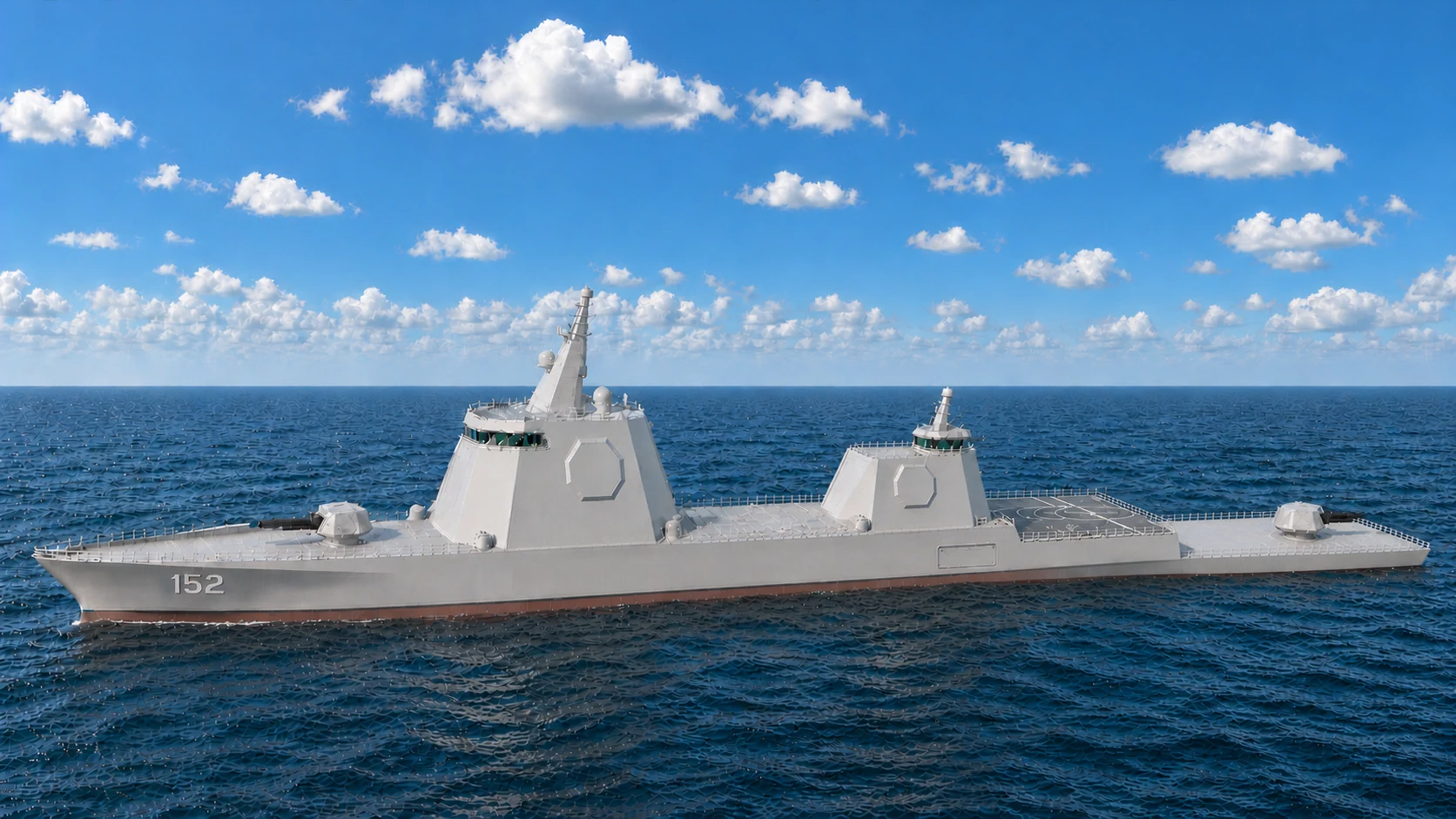
Current DDG-152 visual baseline with locked vertical geometry and aft-aligned ATC.
Mission and Role
Backbone multi-mission escort with primary AAW/BMD emphasis, plus maritime operations detachments, ASW net contribution, and distributed strike integration.
Key Dimensions and Performance
- Length 650 ft, beam 88 ft, draft 24 ft, displacement about 15,000 tons.
- The 24-ft figure remains the hull-design draft target; overall navigational draft with the enlarged Odyssey units remains a naval-architecture output.
- Growth envelope: 18,000 tons is the conditional 20 percent naval-architecture limit, not 3,000 tons of spare payload. Added displacement must preserve stability, structure, draft, freeboard, propulsion margin, speed, maneuverability, and endurance.
- Vertical geometry: 65-ft forward superstructure including bridge; 40-ft aft aviation superstructure with a 25-ft clear hangar and one 15-ft air-ready/briefing level. ATC sits above with its aft face flush to the aft bulkhead and is additional to the 40-ft aft-block height.
- Crew: 320-350 full fighting complement, heavier than austere automation models so the ship can sustain maintenance, proper watches, and combat-system readiness.
- Berthing capacity: 380, preserving margin for mission detachments, trainees, and surge support loads above standard crew.
- Hull scale intent: heavy destroyer / small-cruiser-weight combatant kept near Zumwalt class rather than pushed deep into CAG displacement territory.
- Propulsion set includes three fully azimuthing Odyssey pods rated at 25MW continuous and 27MW short-duration objective each, three LM2500+G4 gas-turbine generators at 35MW each, six 8MW-class Fairbanks Morse Defense PA6B STC diesel-generator packages, and four 10MW peak PRIME battery modules.
- Speed profile: the current powering estimate is about 31.5 kts at full continuous pod output and about 32.5 kts at the short-duration objective rating. Final speed requires model-basin, propulsion, cavitation, and resistance validation.
- Diesel-dominant operation remains about 18 kts, with battery-only operation reserved for shorter concealment and positioning windows rather than sustained transit.
- Weight-control rule: the DDG stays near 15,000 tons by choosing mission-appropriate IWMs and IMMs at build, not by carrying every heavy future option in the first-flight baseline.
Why This DDG Punches Above Typical Destroyer Class
- Ideal hull concept: the DDG is a larger, harder-driving blue-water combatant hull built for speed, maneuver, radar weight, VLS density, and damage tolerance without drifting into exotic geometry.
- Bow form: long bulbous bow with a fine, flared entry that keeps the ship dry, efficient, and controllable in rough water while carrying heavier topside combat weight than the FFG.
- Mid-body form: broad, high-freeboard conventional monohull with enough beam and waterplane area to support large radar arrays, heavy VLS batteries, layered CIWS, and later DEW growth without compromising blue-water seakeeping.
- Underwater body: deep centerline keel, stable lower-hull flare, and bilge keels, with aft-body flow shaping optimized for turn response, pod efficiency, cavitation control, and combat-speed handling rather than ASW quieting alone.
- Stern form: conventional stern with spoon-shaped recessed pod sections sized for high-energy maneuver, clean pod inflow, survivability, and later growth in combat-system weight and power.
- Why these features fit the class: the DDG carries more combat weight and therefore needs stronger waterplane support, cleaner high-speed flow, better turning response, and more aggressive stern shaping around the pod wells so it can fight fast and maneuver hard under load.
- Program position: this DDG is not meant to be a marginal improvement on a Burke. It is meant to fight above normal destroyer class in magazine depth, terminal defense density, and upgrade headroom while staying below CAG scale.
- Why it matters: one of TriSeadon's intended advantages over Burke-style assumptions is not living with a thin last-ditch defense model built around essentially one CIWS station and a smaller terminal-defense envelope.
- Terminal-defense density: the DDG combines 5 locked Cerberus positions for integrated CIWS, missile, and energy payloads with 10 locked SCUTUM positions for certified 30 mm, .50-caliber, MANPADS, and nonlethal local-defense adapters.
- CIWS mix rule: the 5-mount baseline ensures every DDG carries at minimum one energy, one gun, and one missile CIWS layer, with the remaining mounts used to widen sector coverage and increase anti-drone and anti-missile shot density.
- Heavy combat mix: 128 Mk 57 PVLS cells, APM strike capacity with reserved future interceptor-integration pathways, Trinion-L or alternate heavy-fire growth, and a denser terminal-defense network push the ship toward heavy-destroyer or small-cruiser combat effect even if the label stays DDG.
- What keeps it a DDG: the ship still centers on air-defense, missile-defense, speed, maneuver, and escort battle-management rather than becoming a stable aviation-command platform like the CAG.
- Bottom line: this DDG is supposed to be a harder-kill, deeper-magazine, more survivable escort than current destroyer baselines, especially in saturation, drone, and terminal-defense fights.
Energy and Propulsion Architecture
- Three energy systems: 8MW-class PA6B STC diesels for endurance cruise, station keeping, and ship-service loads, LM2500+G4 turbines for high-speed combat maneuver and high-demand power, and PRIME battery banks for shorter electric-only concealment windows, ride-through reserve, and peak combat load support.
- Combat role effect: the DDG's air-defense and DEW burden makes power management central to the class, not a background engineering issue.
- Baseline propulsion path: Odyssey pod target architecture with common fleet power-management logic.
- Displacement discipline: the 15,000-ton target assumes no oversized specialty modules are baked into the baseline hull beyond the DDG's primary AAW/strike mission needs.
- Future growth path: stronger batteries, more mature pod survivability, and larger DEW/counter-air loads fit naturally into the DDG block-upgrade lane.
Sensors and Combat Systems
- AN/SPY-6(V)1 with Aegis Baseline 10 and an X-band SPY-6 variant for high-resolution fire-control and terminal tracking, with the class intended to anchor future radar and fire-control growth for fleet air defense.
- AN/SPQ-9B and NGSSR navigation/surface radar components, with SPS-73-class logic only as bridge legacy wording if needed.
- SPEIR/IRST21 EO/IR family and AN/SLQ-32(V)7 SEWIP Block III, with the class intended to carry the strongest dedicated fleet-screen EW burden.
- Aegis Baseline 10, CANES, CEC, Link-16/22, JADC2 integration.
- ASW stack based on AN/SQQ-90 family with VDS and towed systems so the DDG remains a real undersea warfare multiplier while screening the force at speed.
Weapons and Defense
- Mk 57 PVLS architecture (128-cell primary arrangement stated in source block).
- VLS baseline alignment: Mk 57 PVLS family commonality with Zumwalt deployment, integrated through IWM pathways.
- Transition note: Mk 41 VLS IWM stop-gap path remains active for legacy/standard missile compatibility until Mk 57 PVLS missile certification and production are fully re-established.
- APM cell set supports large-magazine hypersonic strike; future counter-hypersonic interceptor use depends on Navy selection, physical compatibility, safety qualification, combat-system integration, and certification.
- Gun baseline: one forward Mk 45 Mod 4 plus SCUTUM-mounted Mk 46/Mk 38-family 30 mm options and Mk32 torpedo tubes.
- HELIOS/ODIN DEW layer, RAM launchers, 5 CIWS/Cerberus-compatible terminal-defense mounts, and Nulka/SRBOC decoys.
- Three weapon families: missile battery for AAW/BMD/strike, gun battery for sustained surface and shore fires, and energy-defense battery for drone/missile/endurance defense.
- Close-in defense requirement: the DDG uses 5 Cerberus positions and 10 separate SCUTUM positions. Cerberus provides at least one energy, one gun, and one missile CIWS layer; SCUTUM supplies the distributed 30 mm, .50-caliber, MANPADS, and nonlethal force-protection layer. Availability and effectiveness remain payload- and integration-dependent.
- Future weapon path: Trinion-L or alternate heavy-gun IWM, Navy-certified counter-hypersonic interceptors, and larger Cerberus/DEW defensive packages remain DDG growth options after qualification.
Offense-Defense Employment Stack (Data-Dump Integration)
- Sensor-to-shooter chain: SPY-6 plus fire-control and EO/IR/EW tracks fused in Aegis for rapid assignment of VLS interceptors, DEW, and Cerberus terminal mounts.
- Offense lane: Mk 57 PVLS/APM strike support with Mk 45 Mod 4-backed naval fires for sustained surface and shore support.
- Defense lane: DDG serves as the task-group anti-air and anti-missile shield with layered RAM/CIWS/DEW/Cerberus and integrated decoy warfare, especially for drone and missile fights in constrained waters, straits, gulfs, and inlets.
- DDG large-bay emphasis: VDS/towed-array and ASW/UxV IMMs to preserve escort ASW performance while carrying AAW load.
- DDG ISO emphasis: comms relay, EW/SIGINT, counter-UAS, and cyber modules to reinforce fleet battle-network resilience.
Aviation and Modules
- 125' x 80' flight deck and three enclosed hangar bays: one dedicated bay for each of the 2 mission-configured MH-60 helicopters and one dedicated UAV bay for maintenance, payload preparation, launch and recovery equipment, spares, and future VTOL growth.
- Fleet-standard hangar geometry: the aft hangar face remains vertical and planar through every door's complete operating envelope. Door travel, aircraft clearance, apron movement, and flight-deck approach remain unobstructed; stealth faceting may resume above the headers and around the outboard structure.
- Aviation growth standard: expanded flight-deck, enclosed-hangar, and UAV-deck capacity reserves power, data, fueling, tie-down, maintenance, and traffic-control margin for future VTOL drones. MV-22 basing and routine Osprey operations are outside the DDG design baseline.
- Aviation baseline: 2 mission-configured MH-60R/S helicopters plus a mission-selected MQ-19 Aerosonde, MQ-27 ScanEagle, RQ-21 Blackjack-compatible, or follow-on small-UAS detachment.
- Air role logic: the DDG normally emphasizes SAR, personnel recovery, medevac, utility support, and organic ASW while tailoring its MH-60 mix and modular UAV payloads to the mission.
- ATC radar and landing-control package: escort-scale close-range air-search and recovery radar support, TACAN, IFF, deck-landing aids, and UAV traffic-management support for helicopter and drone operations.
- Future air-wing flexibility: the class can bias toward unmanned ISR relay, additional surveillance packages, or mission-tailored detachment support without changing the core hull role.
- LCB count: 5 (1 longitudinal forecastle, 2 crosswise midships bays arranged fore and aft, plus 2 longitudinal side-by-side stern slide-ins at the waterline).
- ISO bay count: 5 slots.
- DDG module posture balances high-end AAW with mission bays able to host ASW, SOF, or logistics IMMs by deployment cycle.
- Build-weight control: the first-flight DDG uses only the IMM and IWM mix needed for its air-defense and strike-support role, while heavier specialty loads stay in later block or mission-specific paths.
- ISO rapid-swap profile supports high-volume UxV control (UAV, USV, UUV, and mission-assigned UMV payload support), EW expansion, counter-UAS surge, and command-network relay without structural changes.
- ASW contribution model combines shipboard sonar/towed systems with MH-60R prosecution to extend the task-group undersea detection and tracking net.
Special Operations Detachments
- DDG detachment baseline is mission-based and not SEAL-only; packages can be NSW/SEAL, SWCC, VBSS, LEDET, and sniper-team combinations for interdiction and precision littoral operations.
- Every TriSeadon DDG carries at least one of these maritime operations detachments for deployment readiness.
- Sniper teams are not fixed to DDG only; sniper detachments are assignable to CAG, DDG, or FFG by mission profile.
- Mission package integration uses LCB/ISO support for SOF comms, precision fires coordination, and rapid launch/recovery craft operations.
20250812 Class Systems Snapshot | Force-Multiplier + Blue-Water Self-Reliance
- Blue-water persistence model: 45+ day endurance profile and a 10,000 nm planning-range baseline, with JP-5 single-fuel operations and tri-source power for long-duration fleet screening.
- Air-defense concentration baseline in source class sheet: SPY-6 family with Aegis Baseline 10, an X-band SPY-6 variant for high-resolution fire-control and terminal tracking, dual SPQ-9B, dual NGSSR, hemisphere SEWIP Block III, and integrated CEC/Link-16/22/JADC2 control.
- Force-multiplier weapons mix in source class sheet: 128 Mk 57 PVLS cells, APM hypersonic/strike module, one forward Mk 45 Mod 4 baseline gun fit, layered DEW/RAM/CIWS/decoy defenses anchored by 5 terminal-defense mounts, ASW suite with SQQ-90 plus SQR-20 MFTA, and a denser terminal-defense posture than current Burke-style assumptions.
- Independent task-group contribution: organic aviation/UxV support, SOF-capable IMM options, and module-driven reconfiguration for AAW leadership without losing ASW and strike support roles.
Future Growth and Alternate Fits
- Air-defense growth path: the DDG is a natural integration candidate for future Navy-certified counter-hypersonic interceptors and higher-end AAW battle-management inserts.
- Gun-growth path: Trinion-L or other IWM-delivered gun alternatives remain possible if the Navy wants more sustained fires without shifting the class away from its AAW mission.
- Energy-growth path: stronger DEW, improved cooling, and better battery discharge rates are especially relevant to the DDG because of its missile-defense role.
- Mission-growth path: ISO and IMM mixes allow the DDG to lean more toward SOF, EW, counter-UAS, or strike-network support on specific deployments.
FFG-64: Guided-Missile Frigate
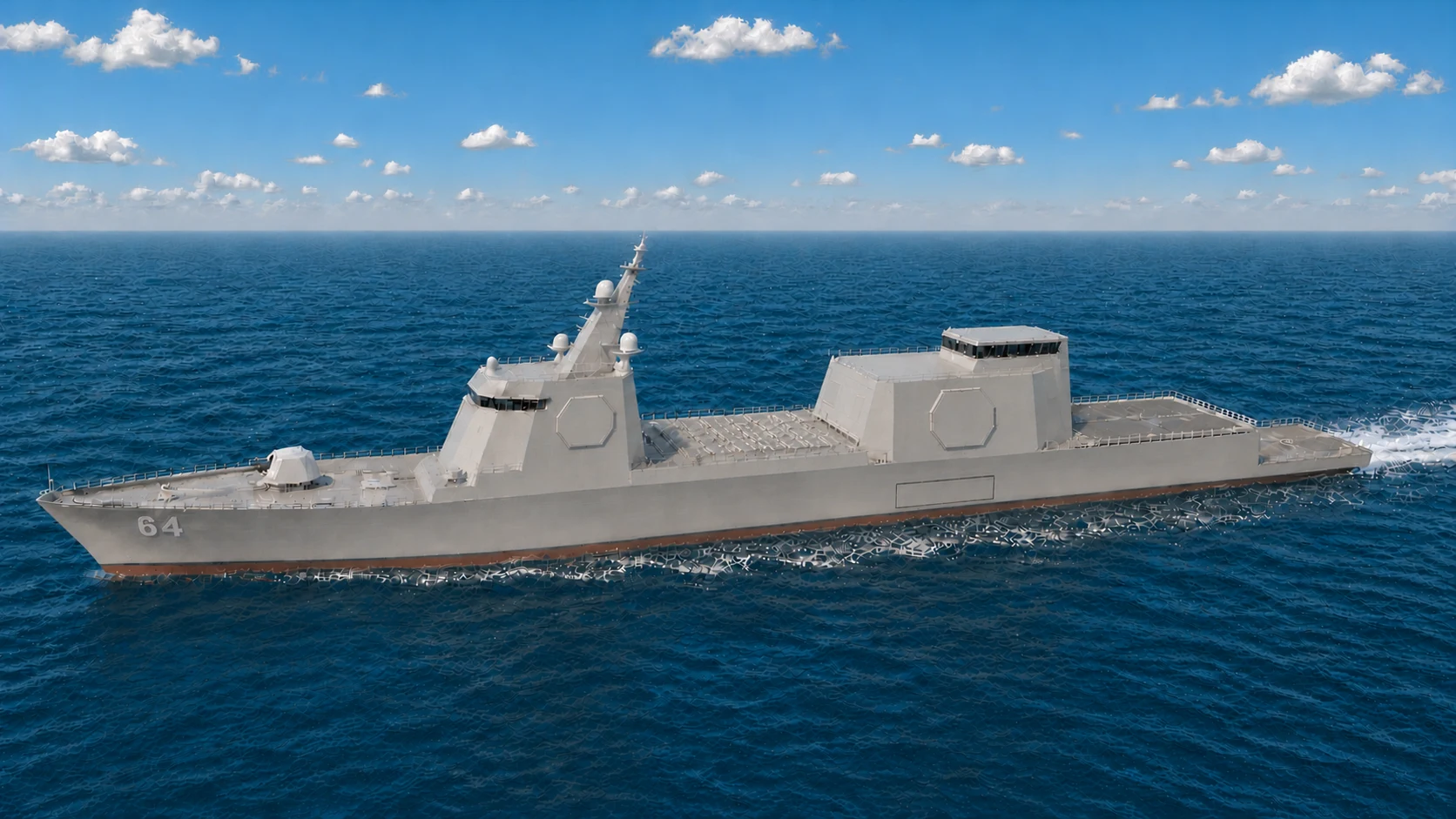
Current FFG-64 visual baseline with locked vertical geometry, Aegis-family aft block, and aft-aligned ATC.
Mission and Role
Quiet blue-water ASW combatant for ocean escort, sea-lane security, persistent undersea hunting, and distributed operations. Littoral control remains a configurable mission, not the class's defining scale or purpose.
Key Dimensions and Performance
- Length 500 ft, beam 66 ft, draft 17 ft, displacement about 10,000 tons.
- The 17-ft figure remains the hull-design draft target, not a certified appendage-inclusive navigational draft. If 17 ft is absolute, the known 23-25MW commercial pod envelope does not fit.
- Growth envelope: 12,000 tons is the conditional 20 percent naval-architecture limit, not 2,000 tons of spare payload. Added displacement must preserve stability, structure, draft, freeboard, acoustic performance, propulsion margin, speed, and endurance.
- Vertical geometry: 50-ft forward superstructure including bridge; 40-ft aft aviation superstructure with a 25-ft clear hangar and one 15-ft air-ready/briefing level. ATC sits above with its aft face flush to the aft bulkhead and is additional to the 40-ft aft-block height. The aft block uses the same scaled Aegis-family faceting and flush radar-array treatment as DDG and CAG.
- Crew: 220-260 full fighting complement, above stripped automation minimums so the ship can stand proper watches and maintain the ASW, aviation, and combat-system load.
- Berthing capacity: 280, preserving margin for mission riders, temporary detachments, trainees, and ASW surge support.
- Hull scale intent: near Flight III Burke-size envelope with frigate mission configuration.
- Propulsion set includes two fully azimuthing Odyssey pods rated at 25MW continuous and 27MW short-duration objective each, two LM2500+G4 gas-turbine generators at 35MW each, four 8MW-class Fairbanks Morse Defense PA6B STC diesel-generator packages, and four 10MW peak PRIME battery modules.
- Speed profile: 28 kts sustained at 80 percent of pod continuous rating is the minimum design point; the current powering estimate is about 30 kts at full continuous pod output and about 31 kts at the short-duration objective rating. Final speed requires model-basin, propulsion, cavitation, and resistance validation. Diesel-dominant operation remains about 18 kts, with battery-only operation reserved for short-duration low-speed ASW quiet-mode work.
Blue-Water ASW Hull and Mission Sizing
- Mission premise: the United States Navy is a blue-water force. The FFG is sized to cross oceans, remain on station, protect a task group, survive a contested deployment, and keep fighting without depending on a nearby home port.
- Ideal hull concept: the FFG is a quiet, conventional blue-water ASW frigate hull optimized around acoustic performance, endurance, aviation, unmanned systems, survivability, and future combat-system growth.
- Bow form: long bulbous bow below the waterline, with a fine raked and flared entry above it for better efficiency, cleaner wave penetration, and stronger reserve buoyancy forward.
- Mid-body form: conventional flared monohull with round-bilge behavior and enough beam for sonar, aviation support, fuel, stores, unmanned operations, machinery isolation, damage control, and future growth, while remaining shaped first for acoustic discipline and endurance.
- Underwater body: deep centerline keel, lower-hull flare out toward the bilge and outer-keel regions, and bilge keels for roll damping, all arranged to support smooth flow, low cavitation, low noise, and stable sensor performance at ASW speeds.
- Stern form: conventional blue-water stern geometry with spoon-shaped recessed aft sections that fair the flow cleanly into the Odyssey pods while preserving later shaft/rudder fallback if needed.
- Why these features fit the class: the FFG keeps cleaner lines, quieter pod inflow, stronger machinery quieting bias, and steadier low-speed behavior because its first job is undersea hunting, not maximum sprint output.
- Operational scale: 10,000 nm planning range and 30+ day independence require fuel, food, aviation stores, sonobuoys, weapons, maintenance space, crew endurance, and damage-control capacity that a regional patrol hull cannot provide.
- Combat-system demand: the hull carries a complete sonar stack, 64-cell missile architecture, gun and torpedo systems, EW, decoys, armor discipline, and 3 Cerberus positions for gun, missile, and energy close-in defense.
- Air and unmanned demand: dual MH-60 operations, shared UAV workshop and support space, DMC, and UUV/USV/UAV launch, recovery, control, charging, maintenance, and payload workflows require real deck and internal volume.
- Future-power demand: reserved generation, distribution, cooling, weight, and module capacity allow stronger sensors, DEW, counter-drone systems, larger unmanned aircraft, and future weapons to enter service without rebuilding the ship.
- Quieting logic: battery operation, electric-drive behavior, careful hull shaping, and Odyssey-oriented propulsion are intended to make the ship extremely hard to detect at slow ASW speeds even though it is not a tiny hull.
- Off-board reach: the FFG's true ASW power comes from the ship plus its helicopters, sonobuoys, drones, unmanned surface and subsurface vehicles, and shared fleet sensor picture.
- Scale-control rule: added volume must serve endurance, quieting, aviation, unmanned reach, survivability, self-defense, maintenance, or certified future growth. It cannot become an excuse to compromise acoustic discipline or load every optional mission at once.
- Bottom line: this is the size required for a globally deployable ASW warship with the air wing, drones, anti-drone defenses, power, weapons, and endurance demanded by the future U.S. Navy.
Energy and Propulsion Architecture
- Three energy systems: diesels for efficient escort endurance, station keeping, and hotel load, turbines for sprint and combat maneuver, and battery reserve for short electric-only ASW quiet-mode work, ride-through reserve, and sensor-focused low-signature operations.
- ASW effect: the FFG's energy model is partly about acoustic discipline, not just top speed.
- Baseline propulsion path: common Odyssey-oriented pod logic sized to frigate displacement and escort requirements.
- Future growth path: better quieting, improved battery endurance, and stronger unmanned-control/sensor loads matter more here than oversized strike-energy expansion.
Sensors and Combat Systems
- AN/SPY-6(V)3F with Aegis Baseline 10 and an X-band SPY-6 variant for high-resolution fire-control and terminal tracking, scaled to the frigate but built to the same family growth logic as the larger hulls.
- 360-degree IRST/SPEIR set with EO/IR and LIDAR references.
- AN/SLQ-32(V)6 SEWIP and Aegis Baseline 10/CANES/Link-16/22/JADC2 baseline, with the escort concept explicitly sized to exceed the current Flight III Burke EW baseline in its own class role.
- ASW system based on AN/SQQ-90 family, VDS/TB-37 MFTA references, and UUV/UAV-enabled sonobuoy operations; this frigate is intentionally built around the fleet's strongest quiet-ASW concentration rather than a reduced escort sonar fit.
Weapons and Defense
- Mk 57 PVLS architecture (64-cell arrangement listed in source).
- VLS baseline alignment: Zumwalt-proven Mk 57 PVLS architecture with TriSeadon IWM insertion model.
- Transition note: Mk 41 VLS IWM stop-gap configuration remains in place for legacy/standard missile compatibility until Mk 57 PVLS missile certification and production are fully re-established.
- APM hypersonic option uses the locked four-tube IWM with 12 CPS rounds when selected, subject to FFG weight, stability, and mission-priority review.
- Gun baseline: one forward Mk 45 Mod 4 with SCUTUM-mounted Mk 46/Mk 38-family 30 mm options and Mk32 torpedo tubes.
- HELIOS/ODIN option, RAM or SeaRAM-compatible launcher, 3 CIWS/Cerberus-compatible terminal-defense mounts, Nulka/chaff decoys, and counter-UAS growth path.
- Six locked SCUTUM positions distribute certified 30 mm, .50-caliber, MANPADS, and nonlethal force-protection adapters around the FFG.
- Three weapon families: escort missile battery, gun battery for economical fires, and energy/terminal-defense layer for survival in drone and missile threat zones.
- CIWS baseline doctrine: the FFG's 3-mount baseline is deliberate: one energy, one gun, and one missile CIWS position minimum on every hull, giving the frigate a full close-in defense triad even while it remains ASW-first.
- Future weapon path: limited Trinion-L or alternate gun growth, better counter-UAS loads, and improved DEW remain possible so long as they do not displace the frigate's ASW-first purpose.
Offense-Defense Employment Stack (Data-Dump Integration)
- Sensor-to-shooter chain: SPY-6/EO-IR/SEWIP inputs with Aegis/CANES fusion prioritize undersea prosecution, escort defense, and cue sharing to DDG/CAG partners.
- Offense lane: precision missile and gun fires with UxV-enabled target development, optimized for distributed ASW and sea-lane control.
- Defense lane: layered short-range defense (RAM/CIWS/DEW/Cerberus-ready mount model) tuned for survivable escort operations in contested zones, especially anti-drone and anti-missile work in close waters, straits, gulfs, and inlets.
- FFG large-bay default: ASW/UxV Operations IMM as primary mission package with VDS/towed array and sonobuoy-heavy workflows.
- FFG ISO default: drone swarm and counter-UAS/EW modules for persistent scouting and local defensive coverage.
Aviation and Modules
- 100' x 60' flight deck and two enclosed hangar bays, one dedicated bay for each of the 2 mission-configured MH-60 helicopters. UAV maintenance, acoustic or ISR payload preparation, compact storage, launch-and-recovery equipment, spares, and future-growth support use shared aviation workshop and deck-support spaces.
- Fleet-standard hangar geometry: the aft hangar face remains vertical and planar through every door's complete operating envelope. Door travel, aircraft clearance, apron movement, and flight-deck approach remain unobstructed; stealth faceting may resume above the headers and around the outboard structure.
- Aviation growth standard: expanded flight-deck, enclosed-hangar, and UAV-deck capacity reserves power, data, fueling, tie-down, maintenance, and traffic-control margin for future VTOL drones. MV-22 basing and routine Osprey operations are outside the FFG design baseline.
- Aviation baseline: 2 mission-configured MH-60R/S helicopters plus a mission-selected MQ-19 Aerosonde, MQ-27 ScanEagle, RQ-21 Blackjack-compatible, or follow-on small-UAS detachment; ASW deployments normally favor MH-60R.
- Air role logic: the FFG combines its MH-60 mix and modular small UAS with persistent dipping-sonar, sonobuoy, prosecution, and over-the-horizon ASW cueing rather than assault lift.
- ATC radar and landing-control package: frigate-scale close-range air-search and recovery radar support, TACAN, IFF, deck-landing aids, and UAV traffic-management support for dual-helo and scout-drone operations.
- Future air-wing flexibility: UAV-heavy ISR or local counter-UAS support can expand through ISO/module choices without changing the frigate's base air detachment logic.
- LCB count: 3 (1 longitudinal centerline forecastle bay for the Mk 45 Mod 4 path, 1 longitudinal centerline midships missile or mission-system bay, and 1 longitudinal centerline stern slide-in bay for boat handling, towed arrays, or another certified mission fit).
- ISO bay count: 3 deck slots.
- FFG mission-bay baseline favors ASW unmanned operations with launch-recovery and mission-control density over amphibious lift payloads.
- ISO posture prioritizes rapid package shifts between drone ISR, EW support, counter-UAS, and comms relay for distributed escort operations.
UDT and Precision Littoral Detachments
- Every FFG baseline includes UDT-capable detachment support for reconnaissance, obstacle-clearance support, and littoral strike cueing.
- Littoral control tasking includes mine laying, counter-mine operations, port and channel clearance, and green-water naval denial support.
- UxV control package supports coordinated UAV/UUV/USV and swift-boat employment for shallow-water screening and access control.
- Sniper teams are mission-assigned as needed and can embark on any class (CAG/DDG/FFG), not FFG-only.
- FFG detachment concept is synchronized with ASW-forward operations to extend sensing and interdiction reach in constrained waters.
20250812 Class Systems Snapshot | Force-Multiplier + Blue-Water Self-Reliance
- Blue-water independence model: 30+ day endurance profile and a 10,000 nm planning-range baseline, with single-fuel JP-5 operations and tri-source power with silent-running battery windows for ASW-forward persistence.
- ASW sensor concentration baseline in source class sheet: SPY-6 family with Aegis Baseline 10, SPQ-9B/NGSSR, SEWIP Block III, full CEC/Link-16/22/CANES/JADC2 pathways, and complete SQQ-90/SQR-20/CAPTAS-4 undersea stack, intentionally sized to overmatch conservative frigate ASW baselines.
- Force-multiplier weapons and defense in source class sheet: 64 Mk 57 PVLS cells, APM strike module pathway, Mk 45 Mod 4 baseline, torpedo tubes, and layered short-range defense built around 3 CIWS/Cerberus positions plus RAM/DEW/decoys for escort survivability.
- Organic sea-control package: dual-helo and UAV integration, mine/ASW/UxV IMM options, and ISO mission modules that let the frigate hold undersea control while extending group sensing and strike cueing.
Future Growth and Alternate Fits
- ASW-growth path: improved towed systems, unmanned undersea integration, and better quieting are the most natural future upgrades for the FFG.
- Defense-growth path: better counter-UAS and short-range defensive endurance can scale through Cerberus, DEW, and ISO module growth without turning the FFG into a mini-DDG.
- Gun-growth path: heavier gun options remain secondary and must not compromise the ASW/escort mission baseline.
- Mission-growth path: littoral control, mine warfare, and UDT-enabled green-water denial remain the most credible alternate emphases for the class.
Technology Baseline Clarification
Flight I Bridge Baseline (Not Counted as New-to-the-World Tech)
- Flight I ships may begin with CDS-family consoles, electric power to shafts, 8MW Fairbanks Morse Defense PA6B STC generator sets, LM2500+G4 turbines, ISO mission modules, APM pathway alignment, CDS-derived missile-control logic, and Mk 57 PVLS architecture as already fielded or field-adjacent bridge technologies.
- The purpose is to keep the first hulls buildable and credible without forcing the program to wait on every future TriSeadon-specific insertion.
Program Insertion Rule
- No class flight, block, series, or release introduces more than three major new technologies at one time.
- If a technology is not ready, the ship does not wait; a stop-gap path is used and the system is inserted on the next eligible flight or refit.
- The intent is controlled fleet learning, not maximum novelty on the lead hull.
Hull-Independent Technology Ladder
TriSeadon is not dependent on approval of one exact concept hull. The common interfaces, production data, qualification methods, software pathways, training, logistics, and modernization rules are designed to transfer to the final Navy-approved FFG, CAG, and DDG designs and to any later separately authorized derivative, including a possible BBG study. Every hull still requires class-specific naval architecture, integration, safety, shock, signature, survivability, and certification work.
- Fielded baseline: identify a current in-service or already qualified system that can perform the required mission when the ship is built.
- Integration step: adapt that mature system to the controlled TriSeadon mechanical, electrical, cooling, data, software, handling, and support interfaces.
- Development step: compete, prototype, and test the improved system off ship without holding hull construction hostage.
- Certification gate: prove performance, safety, cybersecurity, security, shock, environmental qualification, producibility, maintainability, training, spares, and support before fleet insertion.
- Objective insertion: install the certified system on the next eligible hull, lot, or flight, then backfit earlier ships during the scheduled 60-month refit when the engineering case supports it.
- Fallback retention: do not remove the mature baseline from the production and support plan until the successor is accepted, its production source is qualified, and DLA has the required spares, tooling, documentation, and inventory.
Technology RFP and Ownership Rule
- Every clean-sheet TriSeadon technology RFP states before bidding that newly created foreground IP and its reproducible production baseline will be owned by, or placed under equivalent perpetual controlling rights of, the United States Government.
- The rule applies to Odyssey, AEGIR, PRIME, ATLAS, ONE-Consul, LCB, IWM, IMM, ISO interfaces, Cerberus, SCUTUM, Trinion, and later new program technologies.
- Pre-existing privately funded background IP remains protected and must be disclosed before award. Existing products enter through a rights audit, negotiated better-value license, temporary bridge, or government-owned replacement competition.
- Once production is awarded, no new capability change enters that ship, module, or system. Improvements move to the next hull, lot, flight, or scheduled 60-month refit. Current production changes are limited to verified defect, safety, cyber, security, legal or regulatory, and unavailable-part form-fit-function corrections under government configuration control.
Open the complete foreground-IP rule | Open the legacy replacement pipeline
Flight I Counted New Technologies
- New tech 1: class-specialized TriSeadon hull architecture.
- New tech 2: DMC warfare space built into every hull from first construction flight.
- New tech 3: LCB modular integration standard as the permanent build-in pathway for future IWM and IMM swaps.
Planned Insertion Waves After Flight I
- Flight II: ATLAS, AEGIR, and Odyssey pods after certification.
- Flight III and first CAG wave: Cerberus, ONE-Consul, and PRIME.
- Flight IV FFG and CAG Block II heavy-combat wave: Trinion gun insertion plus the approved next wave of IMM, IWM, ISO module, sensor, radar, sonar, and UxV growth by class need.
Certified Current Tech (Not Counted as New Tech)
- Mk 41 VLS is an in-service legacy standard (including Flight III Burke use today).
- Mk 57 PVLS family as primary architecture.
- TriSeadon stop-gap: Mk 41 VLS in a certified IWM path for standard missile compatibility while Mk 57 PVLS missile certification/production is rebuilt.
- Aegis Baseline 10, AN/SPY-6, X-band SPY-6 variant fire-control layer, and AN/SQQ-90 family stack shared across the primary combatant classes, with reserved margin for later SPY radar and fire-control growth.
- Fairbanks Morse Defense PA6B STC diesel generator baseline and GE LM2500+G4 gas-turbine-generator baseline.
- CDS console baseline in service today, with planned transition to One-Consul after formal approval.
Tech Readiness and Stop-Gap Matrix (Proposal Layers Sync)
Program rule: build schedules do not wait for immature systems. Existing systems are fielded first, then upgraded by block/refit after readiness gates pass.
Existing Tech (Field Now)
- Baseline examples: Mk 45 Mod 4, Mk-38, Aegis Baseline 10 with SPY-6 variants, RAM, Mk 41 VLS compatibility, proven turbine/diesel generation.
- Role in TriSeadon: immediate build-start capability and schedule protection.
- Typical integration timing: less than 24 months once shipset procurement is released.
- ROM pricing behavior: integration-dominant spend (lower NRE), typically the lowest-risk cost lane for each block.
Upgradable Tech (Exists, Needs Military Scaling)
- Examples: high-power pod propulsion, scaled DEW increments, unified unmanned control expansion, advanced payload module growth.
- Role in TriSeadon: phased insertion across next block or refit, with fallback paths active in the current block.
- Typical development plus insertion timing: about 2-6 years depending on land-based test and certification outcomes.
- ROM pricing behavior: medium NRE and qualification burden, generally handled as planned block-upgrade lines rather than lead-ship redesign.
New Tech (Requires Full Development)
- Examples: Trinion heavy-gun maturity, potential railgun integration, future Navy-certified counter-hypersonic effectors, and advanced autonomy packages.
- Role in TriSeadon: introduced only by block discipline after validation and module certification.
- Typical development plus insertion timing: about 5-12 years for first operational fleet adoption.
- ROM pricing behavior: highest NRE and test cost lane; funded as independent maturation lines before fleetwide insertion.
Pricing discipline: high-NRE systems are never allowed to force hull redesign or delay steel-cut schedules; stop-gap systems remain active until readiness certification.
Mandatory Stop-Gap Paths
- Guns: Mk 45 Mod 4 IWM path remains baseline until Trinion readiness gates are passed.
- VLS and missiles: Mk 57 PVLS is primary architecture; Mk 41 VLS IWM compatibility remains active while Mk 57 PVLS missile certification and production scale.
- Propulsion: electric-drive power to shaft/rudder baseline remains authorized until Odyssey pod qualification is complete.
- Console/control: current certified CDS/TSCE-derived baselines remain valid until One-Consul transition gates are complete.
- Mission growth: new IMM, IWM, ISO, sensor, radar, sonar, and UxV packages are inserted only inside the next approved three-tech wave or refit package.
Technical Control Baseline (Program-Wide)
- Technology planning baseline is locked to pre-scheduled insertion waves instead of ad hoc feature growth.
- No more than 3 major new technologies are inserted in any single approved release wave.
- Modernization cadence is fixed at 5-year intervals to avoid uncontrolled obsolescence spikes.
- Government retains interface standards, software/control definitions, and technical-data-package control.
- All insertions must meet certified interface and readiness baselines before release.
Linked control pages: Refit Doctrine, Baseline Lock Sheet, and Cost governance.
Technology Tree and Option Paths
Use the technology tree as a planning tool, not a feature list. The main question is whether a capability is baseline, transitional, optional, or approved for later insertion.
Power and Propulsion Tree
Track the current workaround and the end-state power architecture together: GOLAG and power-to-shaft first, then AEGIR, PRIME, and Odyssey once certification gates are complete, with common diesel, turbine, battery, and pod replacement logic across all three classes.
- Current / stop-gap: GOLAG-style mechanical/electric mix, LM2500+G4 gas-turbine generators, 8MW-class Fairbanks Morse Defense PA6B STC diesel generator packages derived from a public 6.72 MWe OEM family, and electric power to shafts.
- End goal: full AEGIR-managed tri-source power with four 10MW peak PRIME modules on FFG and DDG and six on CAG, two AEGIR distribution sections on FFG and DDG and three on CAG, and certified fully azimuthing Odyssey pods rated at 25MW continuous with a 27MW short-duration sprint objective.
- Why both matter: proven power trains stay usable now without breaking the path to the final electric architecture.
LM2500+G4
8MW Diesel Gen
Prime
Odyssey
AEGIR
Weapons and Defense Tree
Explain the baseline weapon lane, the stop-gap launcher path, and the planned end-state insertions: Mk 41 VLS/Mk 57 PVLS alignment, APM strike, SLCM-N reserved integration, Mk 51 AGS family and railgun IWM competitions, Trinion growth, and Cerberus-based terminal defense.
- Current / stop-gap: legacy missile compatibility through certified launcher-module workarounds, Mk 45 Mod 4 gun baseline, and proven close-in defenses.
- End goal: Mk 57 PVLS-centered fleet magazines, APM strike lanes, IWM-driven weapon swaps, Trinion heavy-gun insertion, a rights- and affordability-gated Mk 51 AGS family option, and later railgun-family systems through the same government-controlled interfaces.
- Why both matter: immediate compatibility stays available while preserving the larger weapon architecture the program is trying to reach.
Mk 57 PVLS
APM
SLCM-N Integration
Mk 51 AGS and Railgun
IWM Options
Trinion
Railgun
Cerberus
SCUTUM
Command and Modularity Tree
Show the control and modularity stack as a growth path: current console/control practice, then dedicated DMC, ATLAS-standardized berthing outfitting, and permanent module-control standards.
- Current / stop-gap: CDS-family consoles, conventional control-node layouts, and existing modular interface practice.
- End goal: dedicated fixed DMC warfare spaces, ATLAS-standardized berthing outfitting inside fixed compartments, and standardized LCB/IMM/IWM/ISO integration.
- Why both matter: current control systems remain usable without blocking the target modular-control architecture.
DMC
ONE Consul
ATLAS
LCB
IMM Options
ISO
Dossier RFP and Lessons Addendum
RFP priorities from dossier baseline
- Naval gun modernization path with Mk 51 AGS-derived lessons and fixed-ammunition reliability objectives.
- Azimuthing pod propulsion hardening for combat and endurance operations.
- Containerized lithium-ion power architecture with naval safety controls.
- National IM/ISO production contracts with competitive sourcing.
Dossier evaluation criteria
- Proven performance in related systems and environments.
- Compatibility with shared combat architecture and open interfaces.
- Cost and schedule reliability with domestic sourcing preference.
- Lifecycle support and long-term upgrade viability.
Failure lessons redeployed into TriSeadon
- LCS modularity lessons: use swap modules for support/flex missions, keep combat-critical systems standardized and integrated.
- DDG-1000 integration lessons: avoid bespoke class isolation through common architecture and repeatable interfaces.
- Mk 51 AGS lessons: preserve viable gun-system elements while correcting ammunition and integration risks through block insertion discipline.