12. PRIME Battery Energy Modules
Back to this item in New Technology Catalog
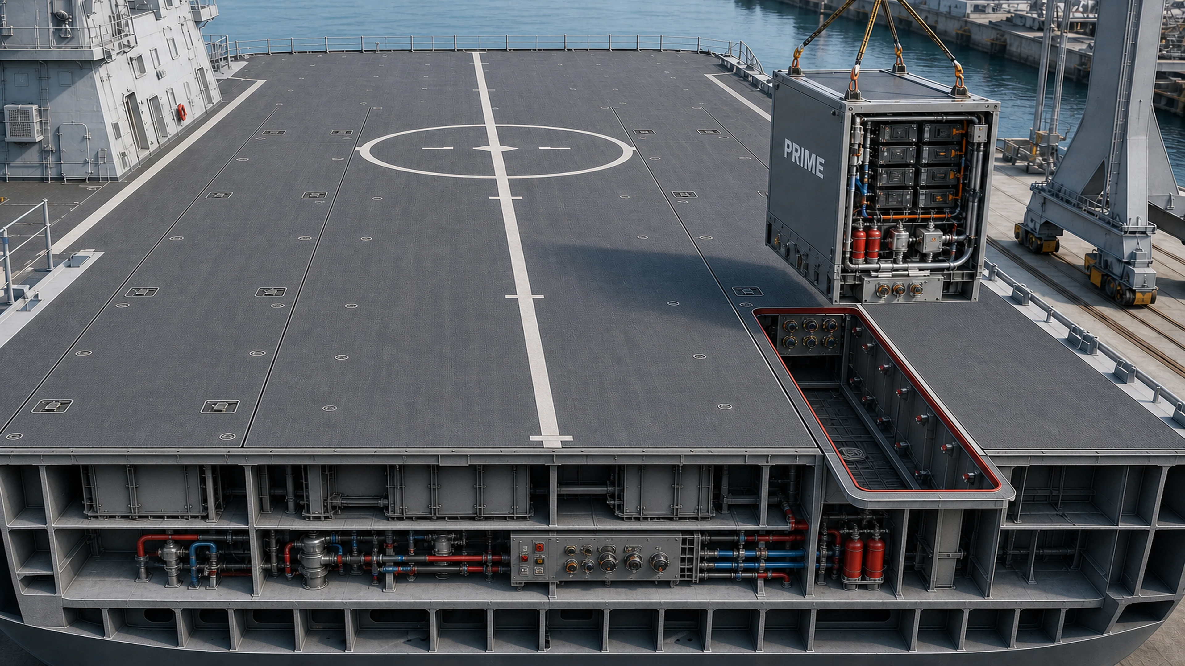
PRIME integral flight-deck concept: there is no separate hatch, cover, or movable deck above a PRIME unit. The hardened nonskid top of each 40 ft x 8 ft x 10 ft module is the flight deck. During an in-port exchange, the complete module and its deck-top surface lift vertically as one unit, leaving only that module's protected well open while every surrounding deck section remains fixed. This cutaway illustrates the six-module CAG reserve-depth arrangement; FFG and DDG use the same module and interface standard in four-module arrangements.
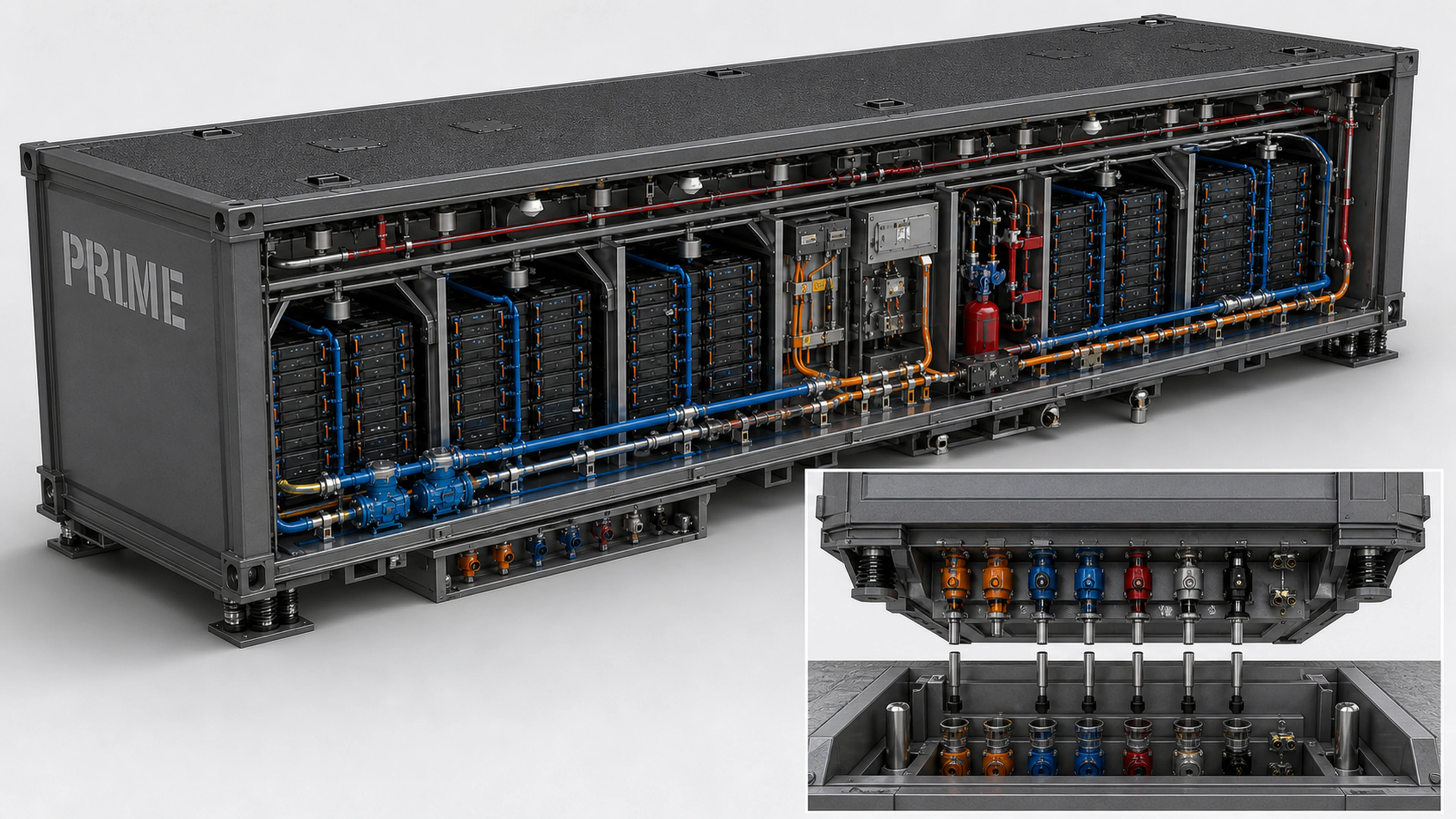
PRIME module anatomy: the 40 ft x 8 ft x 10 ft unit remains one complete crane-lifted assembly, including its unpainted nonskid deck top. Replaceable battery subpacks sit in armored propagation-separated bays. Blue circuits represent redundant liquid cooling; orange circuits represent protected high-voltage distribution; red circuits represent detection and fire suppression. Every ship-service connection terminates in a protected downward-facing plug block on the battery underside. The fixed PRIME compartment carries the matching upward-facing receptor in its floor.
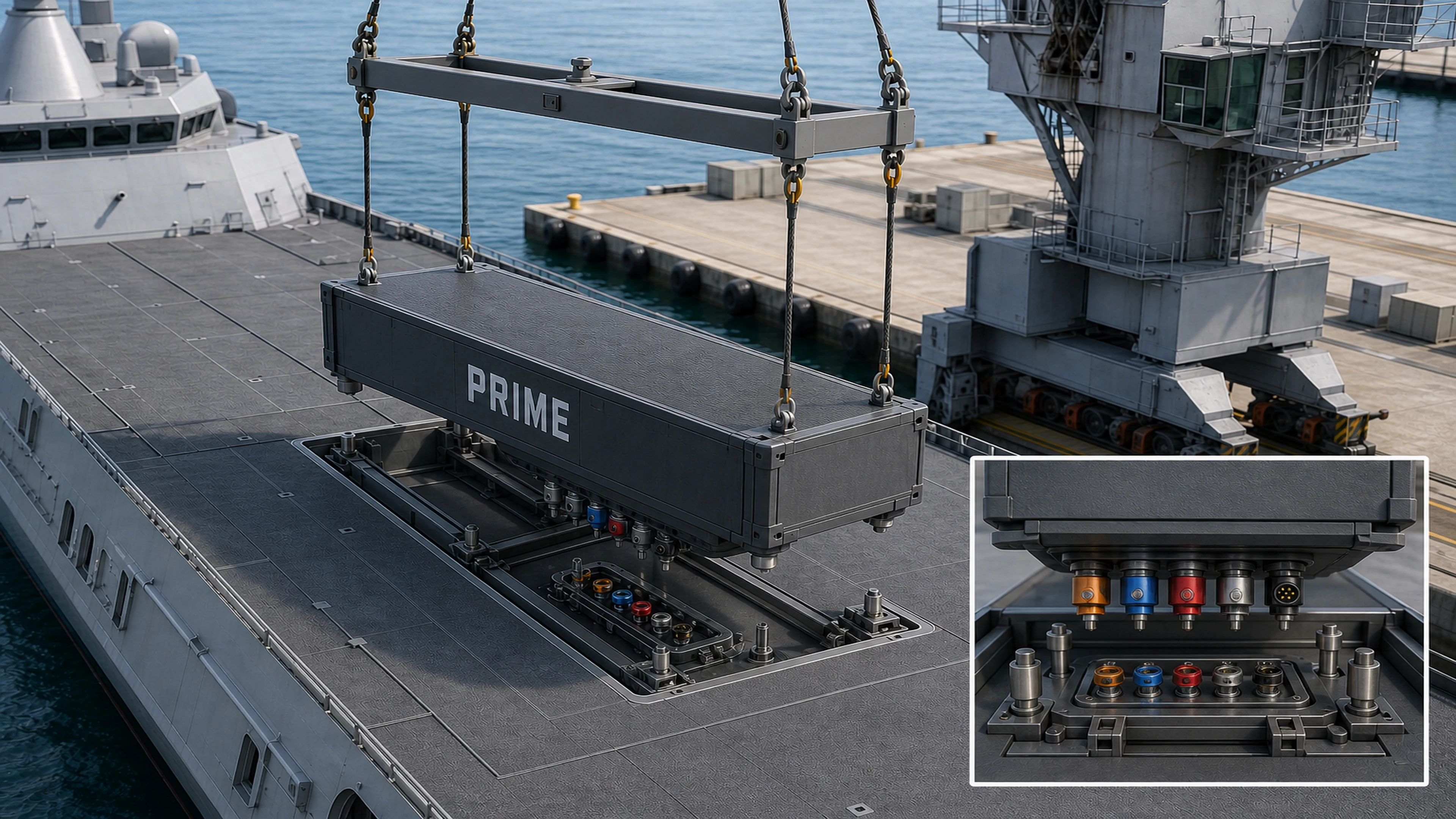
Pier-side guided exchange: a rigid spreader connects to four recessed shackles built into the PRIME deck top so the 40 ft module remains level during installation or removal. Four tapered guide pins and keyed rails engage first, center the module, and prevent rotation. During the final controlled descent, the battery's downward-facing underside plug block snaps into the upward-facing receptor fixed in the compartment floor like a large cordless-tool battery. Mechanical locks then seat the unit while its unpainted nonskid top finishes the flight-deck surface.
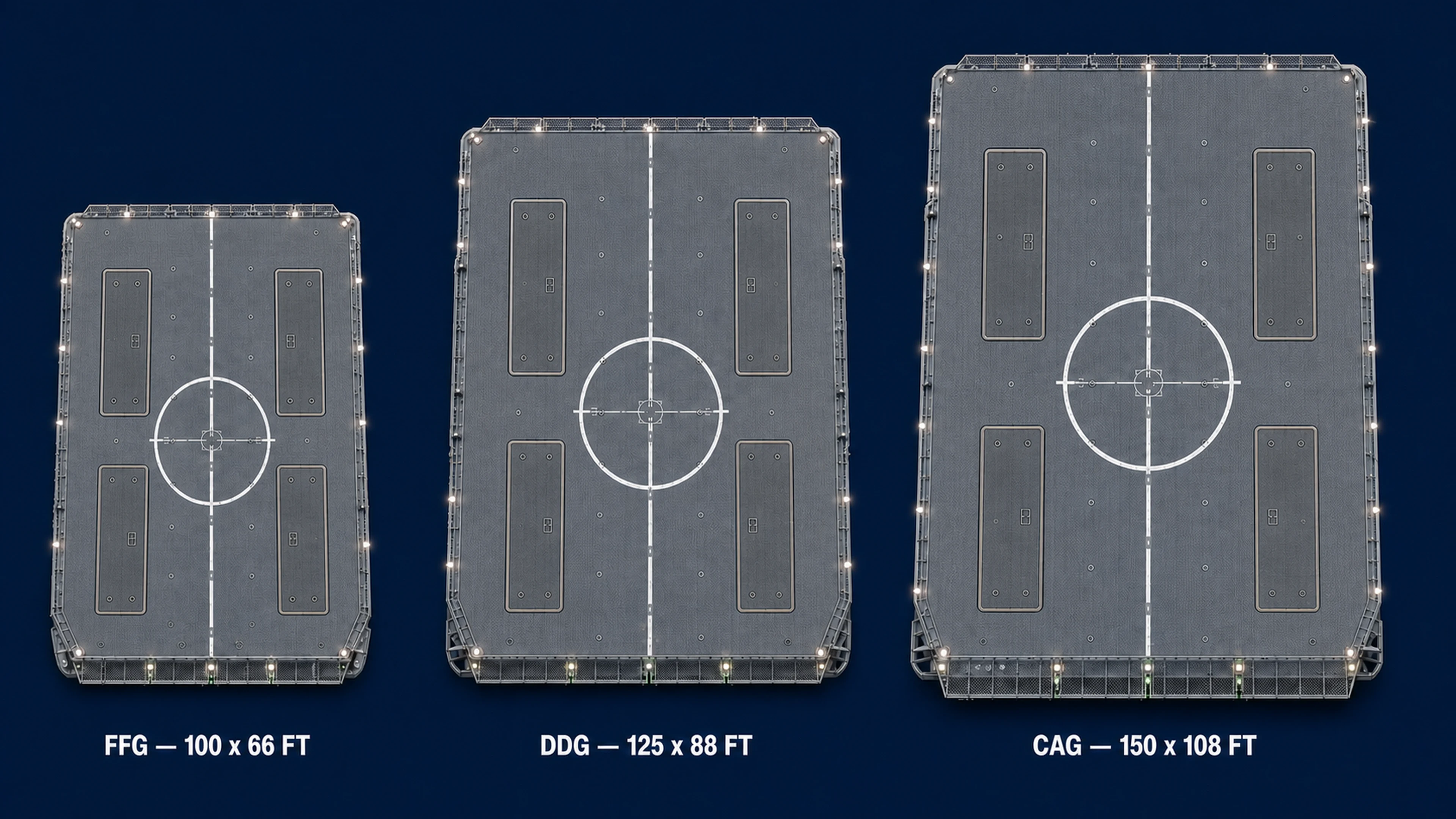
Four-module common-fit study: four identical 40 ft x 8 ft PRIME modules fit as two inboard pairs on the 100 ft x 66 ft FFG deck, the 125 ft x 88 ft DDG deck, and the 150 ft x 108 ft CAG deck. Every well remains at least 15 feet inboard of the port and starboard deck edges so it does not intrude over the covered passageways below. Landing circles, centerlines, safety stripes, and other paint remain on fixed deck structure; every interchangeable PRIME top carries only common nonskid, recessed lifting points, and service covers. Whether the CAG retains four modules or uses two additional modules for six-module reserve depth remains a separate allocation decision.
What It Is
- Acronym meaning: PRIME = Primary & Reserve Integrated Modular Energy.
- Module rating: 10MW peak-power module in the current fleet canon.
- Physical size: 40 ft x 8 ft x 10 ft module envelope.
- Class fit: CAG x6 modules, DDG x4 modules, FFG x4 modules.
- Energy reality: a realistic navalized target is better described as an approximately 4-6 MWh usable-energy module with ship-hardening, thermal controls, fire suppression, gas handling, and armored flight-deck top treatment, not as an unlimited-duration propulsion source.
- Mission use: silent operations, load smoothing, surge power, emergency backup, and ride-through reserve for high-demand combat loads.
- Integration: plug-in modular architecture with built-in lift points / crane-hook attachment points for removal and replacement in port, plus fire-suppression, access, and monitoring interfaces integrated into the hull and flight-deck design.
Why We Are Doing It
- Provide reserve energy for silent operations, surge loads, and future high-demand systems.
- Give the FFG a meaningful electric-only ASW hunt window and give DDG/CAG shorter electric-only masking or positioning windows for force multiplication.
- Support consistent fleet growth without class-unique power redesigns.
- Turn battery replacement into a planned 60-month maintenance action rather than a bespoke depot event.
Used Today / What It Counters
- Used today: containerized battery approaches and IPS-derived power controls are already established in fleet/commercial pathways.
- Counters: power shortfalls during high-demand combat loads and degraded-power casualties.
Current Stop Gap
- Containerized hardened flight-deck-grade battery modules tied into AEGIR-managed ship power architecture.
- Ship remains fully operable without PRIME as a hard dependency.
Next Flight Implementation Steps
- Select and certify flight-approved battery chemistry and safety controls.
- Integrate PRIME through AEGIR control logic and test under casualty conditions.
- Field during planned block windows with no unplanned hull changes.
Options and Styles
- Chemistry Options: chemistry-agnostic reserve-energy framework with qualified baseline chemistry per flight.
- Class Allocation Styles: CAG x6, DDG x4, FFG x4 baseline module counts.
- Mission Styles: silent-operations reserve, surge-load support, casualty-power reserve, and electric-only tactical quiet mode.
Mounting and Integration Particulars
- Installed as module sets integrated through AEGIR-managed power distribution.
- The top of each module forms part of the flight deck surface and must use hardened non-skid deck treatment with no class-unique painted-line dependency that would prevent interchangeability between hulls.
- PRIME wells remain at least 15 ft inboard of the port and starboard flight-deck edges so they do not intrude into the protected structure above the covered passageways.
- All aviation markings remain on fixed deck structure; PRIME tops carry no painted lines so rebuilt modules can move between ships without repainting.
- Four recessed corner shackles connect to a rigid crane spreader for a level vertical lift; their watertight covers return flush when the module is installed.
- Four tapered alignment pins and keyed guide rails engage before the service interface, centering the module and preventing incorrect orientation.
- All standardized power, cooling, ventilation, drain, fire-service, and data plugs face downward from the battery underside; the matching receptor faces upward from the fixed PRIME-compartment floor.
- The final downward travel snaps the underside plug block vertically into the upward-facing receiver; positive mechanical locks confirm full seating before energization.
- Each module includes standardized lift points / hook hardpoints so a port crane can attach directly and pull the battery package vertically during planned maintenance.
- Modules are removed by crane in port; flight-deck operations stop while a module is out, and replacement is a planned maintenance action only.
- Treated as modular energy inserts aligned to the 60-month refit replacement cycle, with removed units routed back through DLA for rebuild and reissue.
Operational Read
- FFG tactical use: with four PRIME modules, the FFG can credibly support a serious electric-only ASW hunt window, but it should be described as a low-speed tactical quiet-mode reserve rather than a high-speed battery sprint profile.
- CAG reserve depth: six PRIME modules provide additional flagship ride-through, combat-load buffering, medical and aviation continuity, and tactical positioning reserve for the fleet's largest electrical load.
- Duration guidance: 2-4 hours is the safer planning figure for meaningful electric-only ASW work, with up to 4-6 hours possible in disciplined low-speed quiet-mode conditions depending on sensor load, ship-service draw, and sea state.
- DDG and CAG use: the larger ships can also go electric-only for shorter concealment, positioning, and force-multiplication windows, but PRIME is not meant to replace their turbine-driven high-speed transit role.
- System role: PRIME is best understood as a tactical reserve, emergency backup, and spike-buffering system that also enables short electric-only mission windows.