CAG Constrained Side Render
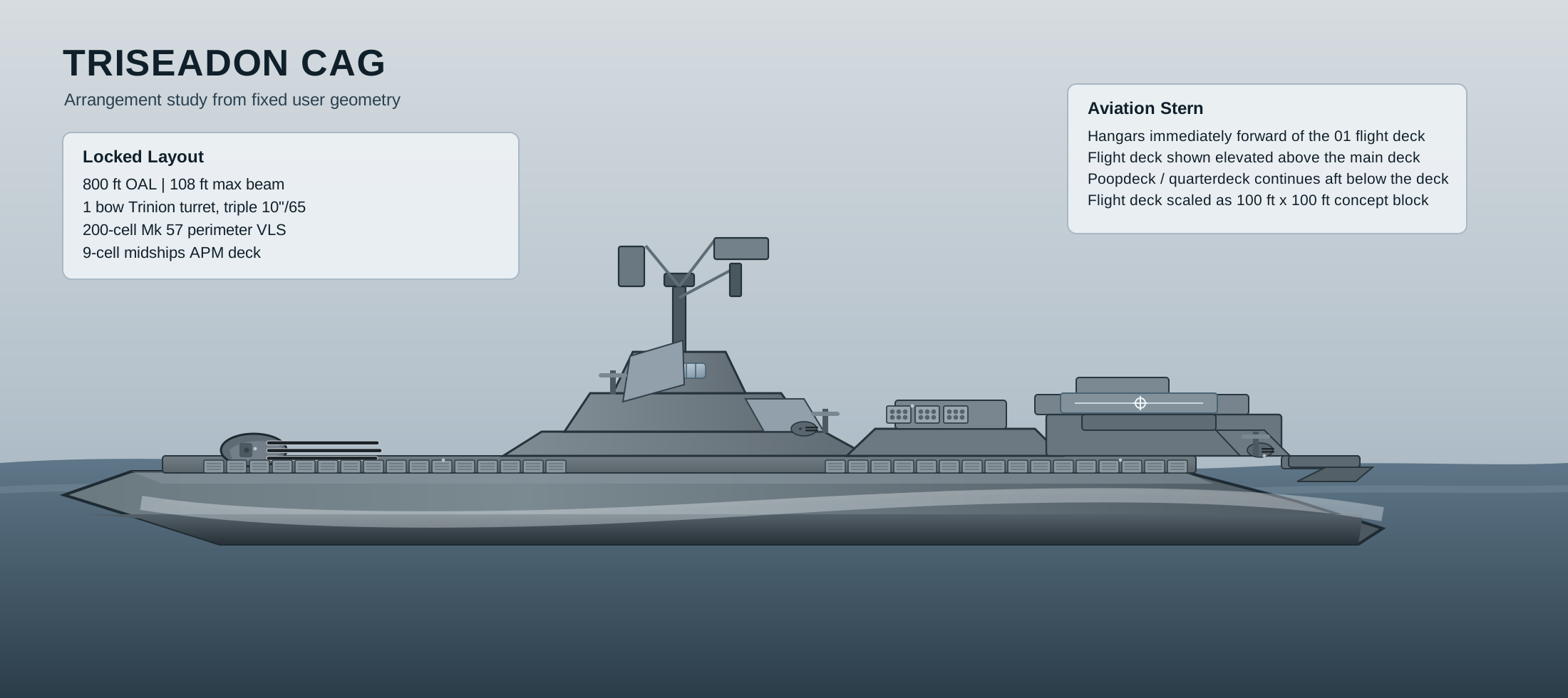
More developed CAG side-profile render showing the heavy gun-and-missile cruiser direction more clearly than the generic fleet silhouette sheet.
Renderings, floorplan-style layouts, technology cutaways, and animated mission-module sequences.
Visual Layer
This page turns the dossier into something easier to understand quickly: fleet silhouettes, deck-layout diagrams, technology cutaways, and looped animated sequences for module insertion rules.
These images capture the visual direction more accurately than the older placeholder sheets. They show the kind of stealth hull language, perspective rendering, internal cutaway, and turret presentation the TriSeadon visuals should be moving toward.
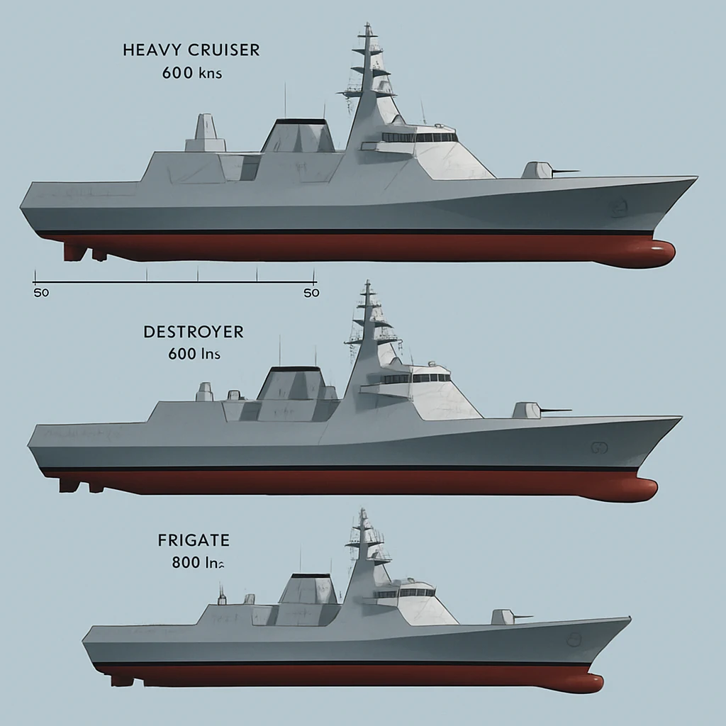
Reference fleet styling board: this is much closer to the intended FFG, DDG, and heavy cruiser visual language than the simplified silhouette sheet.
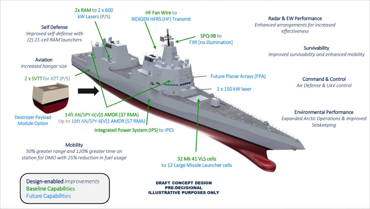
Reference DDG presentation style: stronger sense of hull massing, sensor placement, weapon zones, and explanatory overlays.
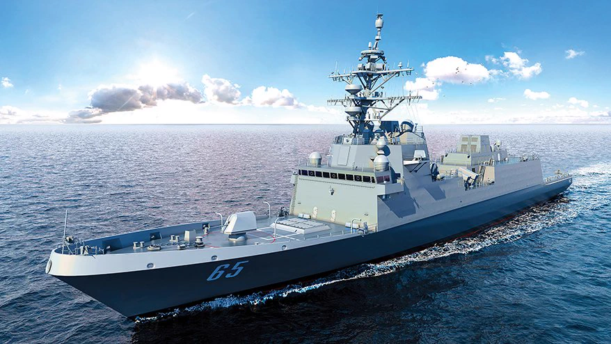
Reference perspective mood: this is the type of real-ship presentation the DDG and FFG need instead of flat placeholder diagrams.
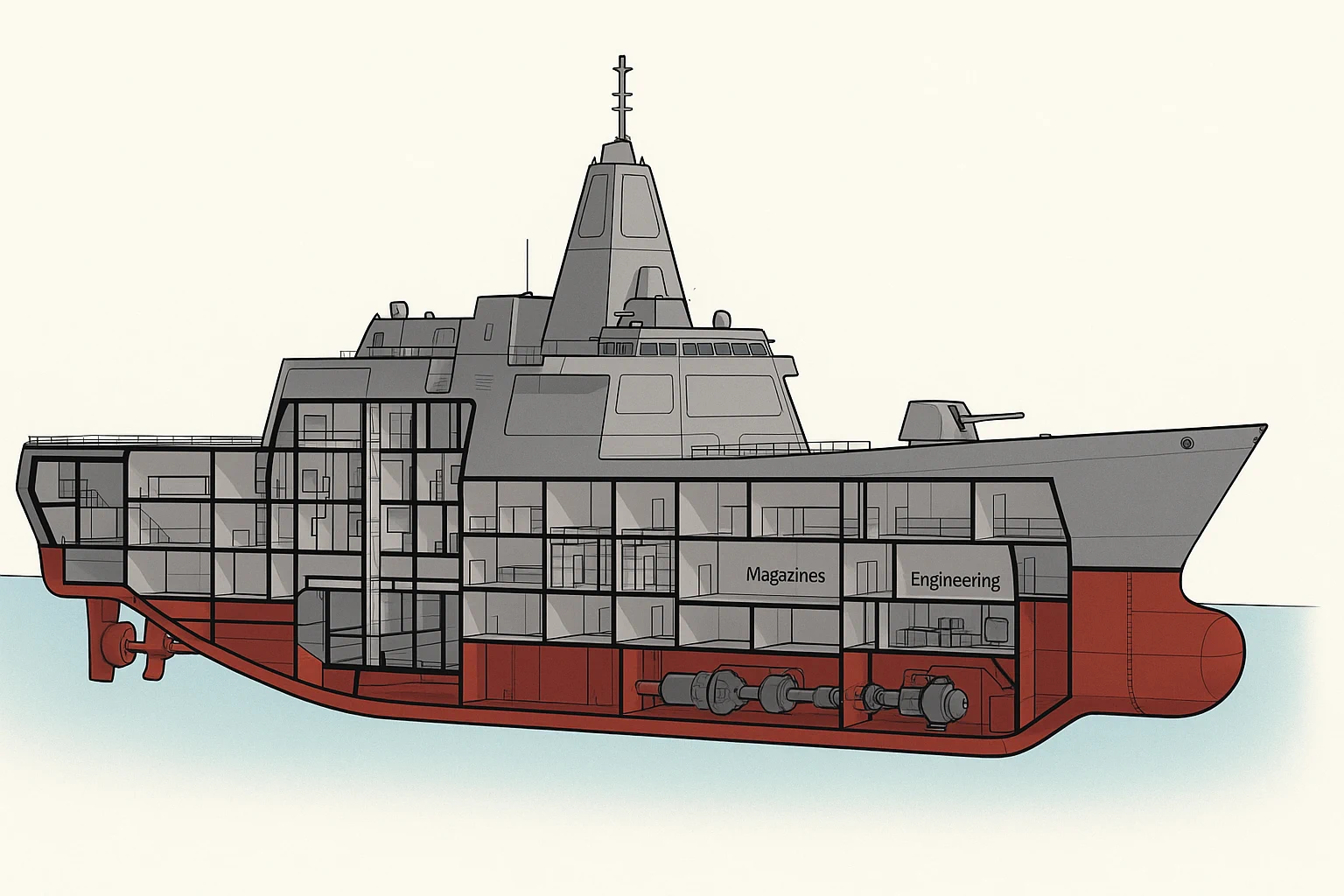
Reference cutaway style: useful model for future TriSeadon section views showing magazines, engineering, and mission spaces inside the hull.
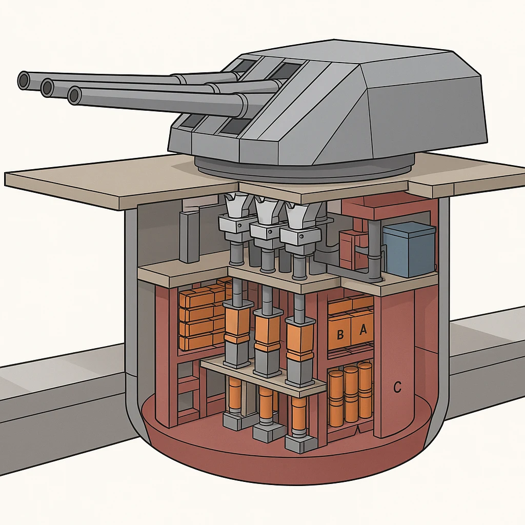
Reference Trinion style: this is much closer to the kind of turret and magazine explanation sheet the site should use for the Trinion system.
FFG-64, DDG-152, and CAG-3 now have dedicated fleet-family concept renderings. They remain conceptual massing studies governed by the locked class dimensions and interface rules rather than final naval-architecture production drawings.
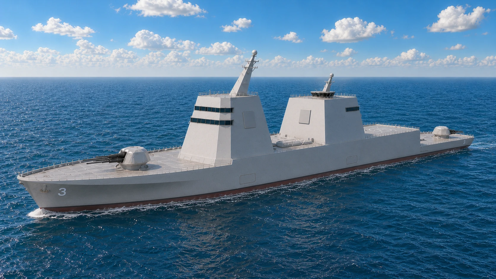
CAG-3 canonical visual baseline: the selected port-bow rendering with two bridge levels, square radar faces, a clearly aft-raked main mast, a half-height aft mast, and the approved aviation and aft-gun-deck relationship.
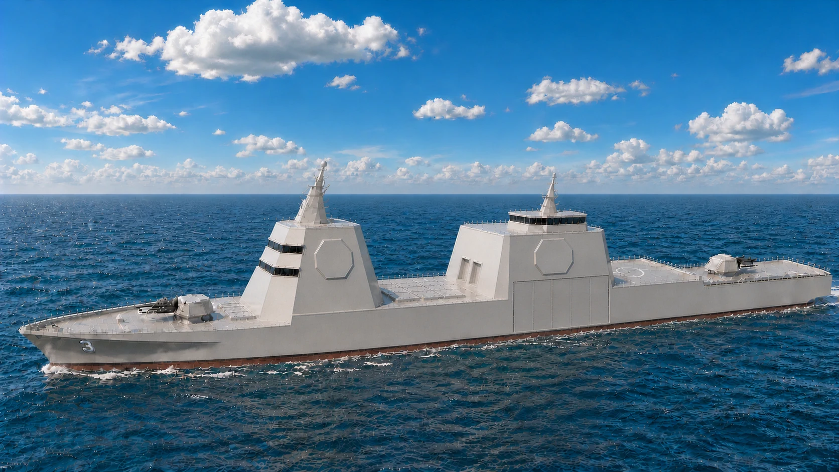
CAG Prior Canonical: retained for visual history after selection of the current port-bow baseline.
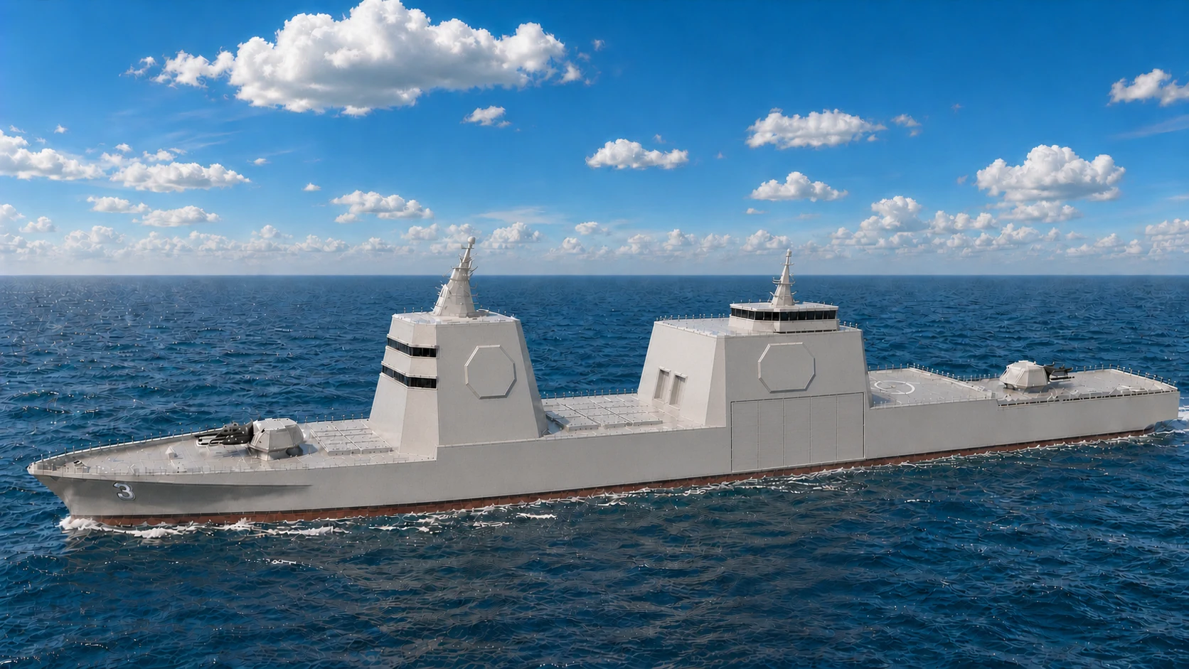
CAG Alternate 1: the preserved prior cruiser rendering with the original superstructure massing.
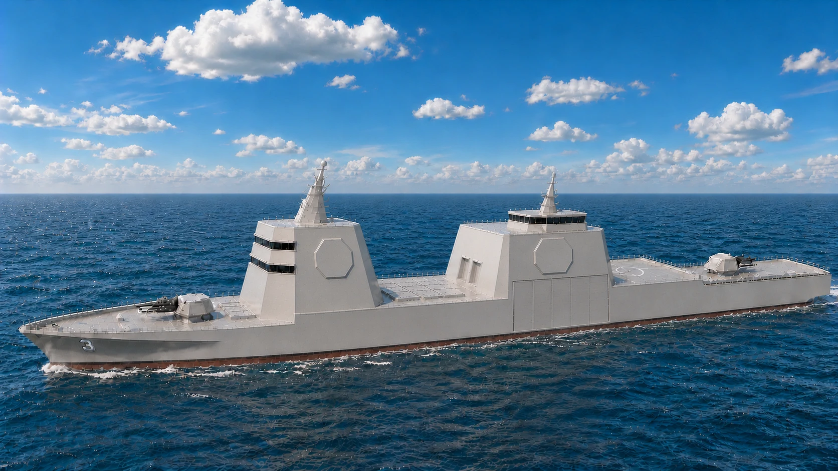
CAG Alternate 2: the initial family-aligned rendering retained before the forward superstructure received its additional aft rake.
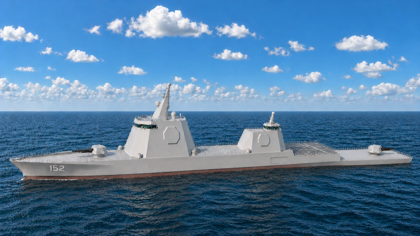
DDG-152 baseline: 65-ft forward superstructure and 40-ft aviation superstructure, with aft-aligned ATC above.
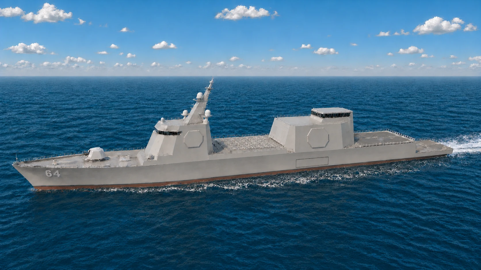
FFG-64 baseline: 50-ft forward superstructure and 40-ft Aegis-family aviation superstructure, with aft-aligned ATC above.
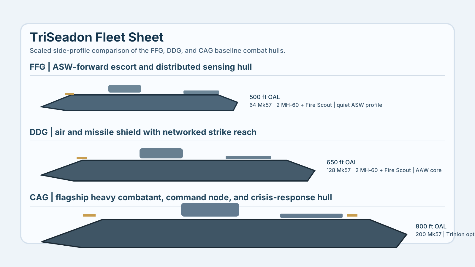
FFG, DDG, and CAG side-profile comparison sheet with baseline role notes and scale relationship.
More developed CAG side-profile render showing the heavy gun-and-missile cruiser direction more clearly than the generic fleet silhouette sheet.
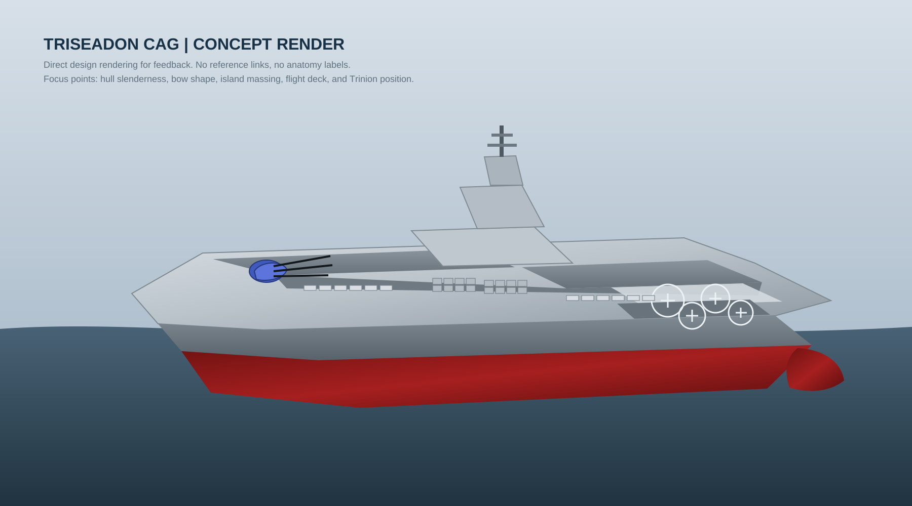
Perspective concept study for the CAG. This is closer to a real rendering pass than the FFG and DDG currently have.
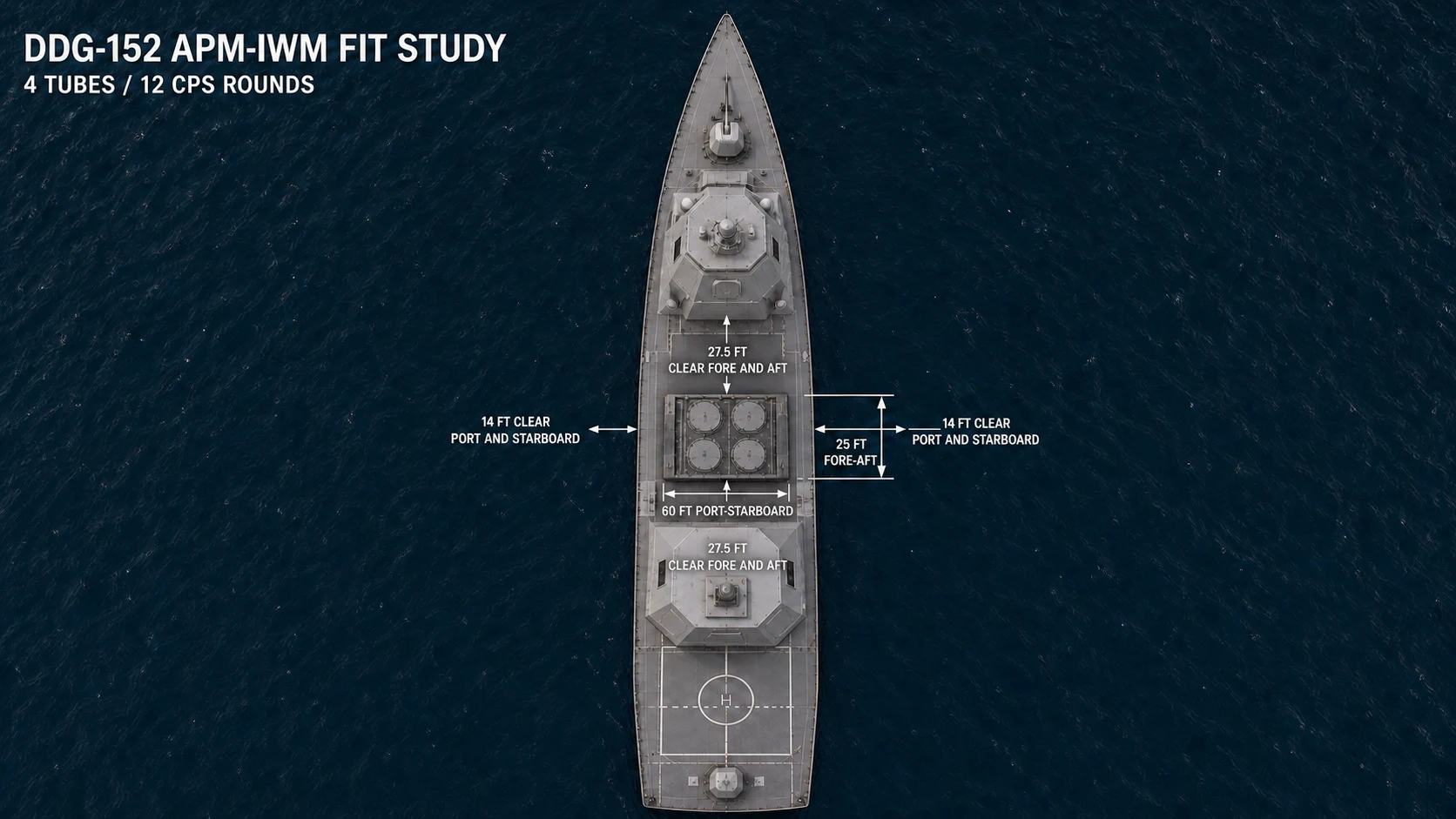
Installed-system study: the locked 60 ft x 25 ft APM-IWM is rotated crosswise in the DDG's 80-ft midships missile-deck zone, with its 60-ft axis port-to-starboard and its 25-ft axis fore-to-aft.
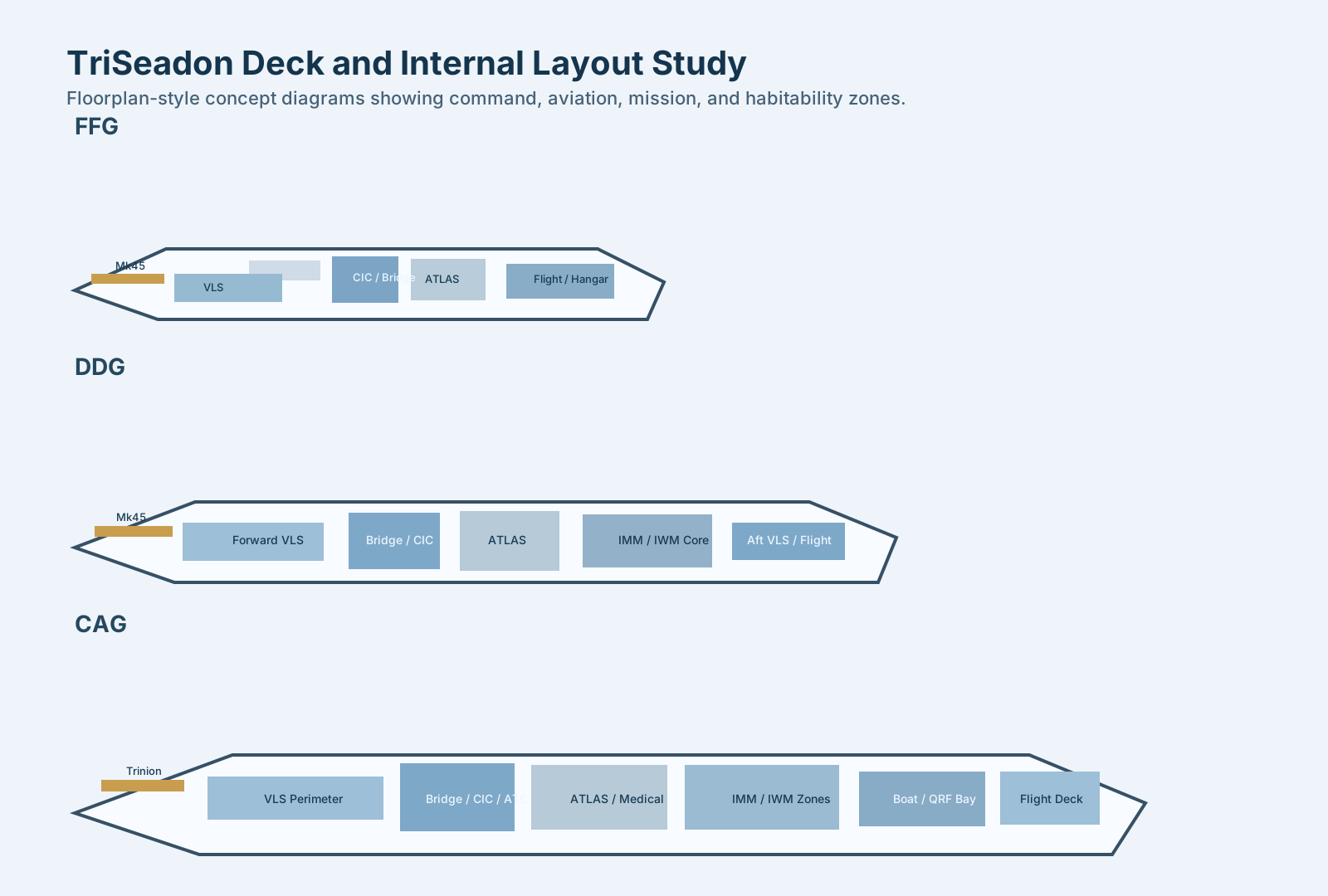
Top-down floorplan-style diagrams showing flight deck, VLS bands, command spaces, boat/module zones, ATLAS berthing blocks, and mission-control spaces.
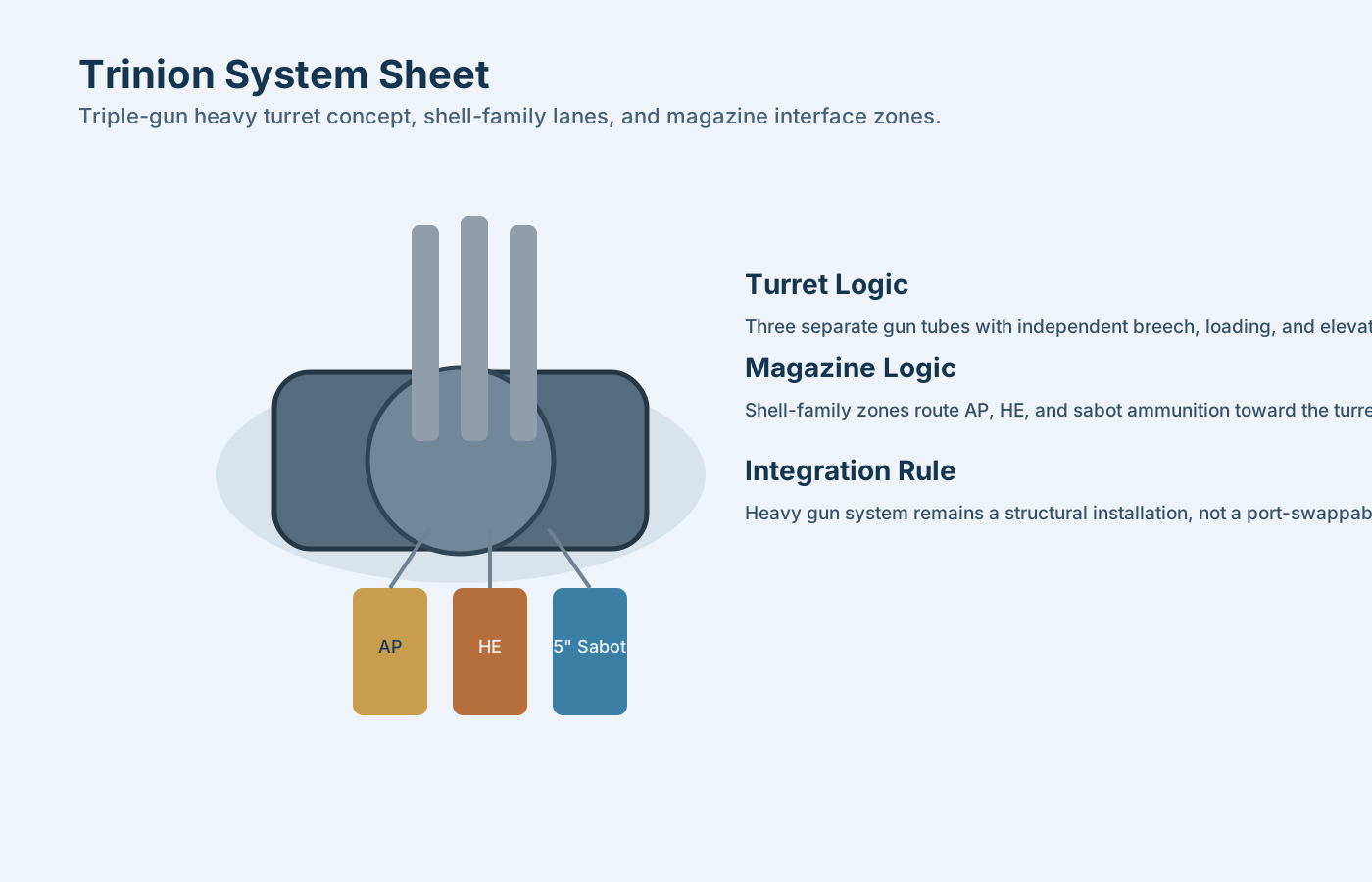
Trinion system sheet showing turret geometry, shell-flow concept, and relationship to the surrounding hull and magazine spaces.

ATLAS provides common berthing-outfit kits inside fixed hull compartments. The ship retains central laundry and retail services, purpose-built food and training spaces, and fixed command, machinery, and damage-control spaces.
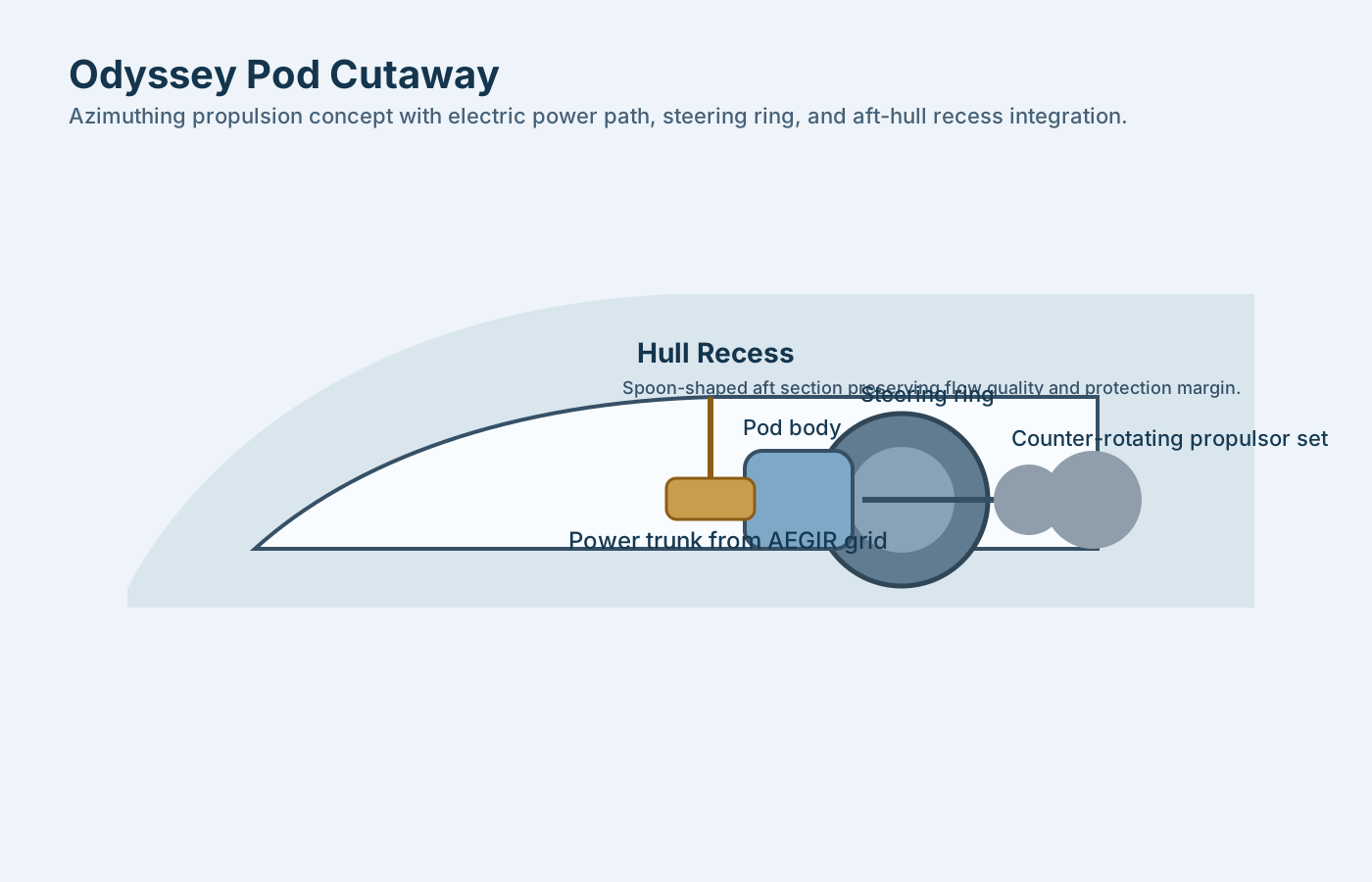
Odyssey propulsion cutaway showing electric power path, steering ring, propulsor assembly, and aft-hull integration logic.
These are short looping sequences, built as native web animations rather than video files, so they stay editable.